
Humidity detector circuit
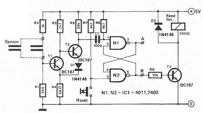
The humidity detector circuit is a project designed to measure and indicate the level of humidity in the environment. This circuit utilizes commonly available electronic components, making it accessible for hobbyists and engineers alike. The fundamental operation of the circuit is based on a humidity sensor, which detects changes in humidity levels and converts these changes into an electrical signal.
The primary component of this circuit is a humidity sensor, such as the DHT11 or DHT22, which provides both humidity and temperature readings. The sensor typically outputs a digital signal that can be read by a microcontroller or microprocessor, such as an Arduino or Raspberry Pi, which processes the data accordingly.
Additional components in the circuit may include resistors, capacitors, and a power supply, which are used to stabilize the sensor's output and ensure reliable readings. An LED indicator can be incorporated to visually represent humidity levels, with different colors or blinking patterns indicating various humidity ranges.
For further enhancement, a display module, such as an LCD or OLED, can be integrated to provide a real-time readout of the humidity levels. This allows for easy monitoring and interpretation of the data. The circuit can also be designed to trigger alarms or notifications when humidity levels exceed predefined thresholds, making it suitable for applications in agriculture, HVAC systems, and environmental monitoring.
Overall, this humidity detector circuit serves as a practical example of how simple electronic components can be utilized to create effective measurement tools in various applications.Humidity detector circuit electronic project using common electronic parts 🔗 External reference
Related Circuits
The only drawback of a single operational amplifier (op-amp) stage is that it inverts the signal, necessitating an additional inverting buffer to restore the original phase if absolute phase is a concern. Various schematics exist for both configurations, but...
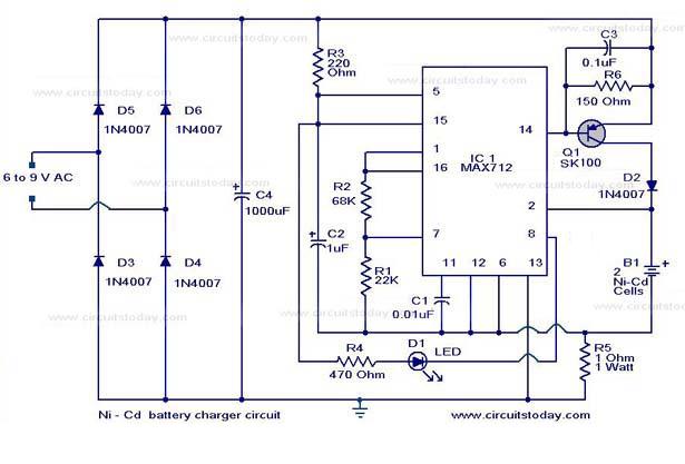
The following circuit illustrates a super fast Ni-Cd battery charger. It is based on the IC MAX 712 and is designed to charge a Ni-Cd battery at a rate of 300 mA. The circuit utilizes the MAX 712 integrated circuit,...
The schematic presented is a project for a simple temperature sensor circuit, also referred to as a heat sensor circuit, which activates an LED in response to heat. The circuit is straightforward to construct and requires only a few...

The circuit is designed to connect in parallel with a telephone, displaying the dialed number using DTMF (Dual Tone Multi-Frequency) signaling. It can also show the number dialed from the receiving party's phone, making it useful for capturing numbers...
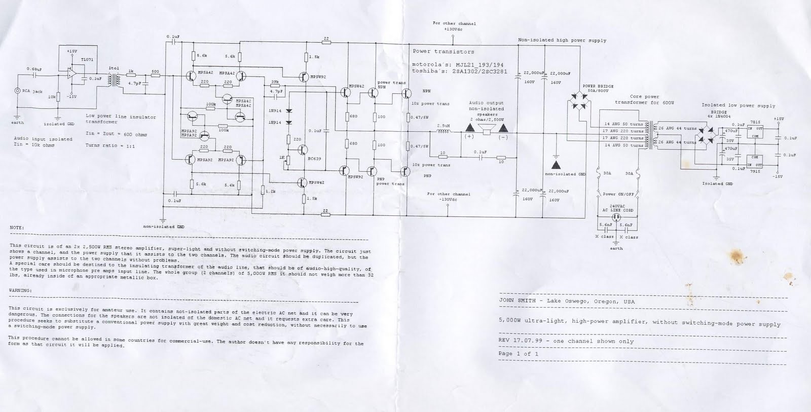
This device is a 2x2, 500W RMS stereo amplifier, designed to be super-lightweight and equipped with a switching-mode power supply. The device features a single channel display and specifies the power output it provides to both channels. The audio...
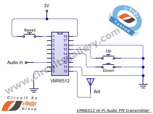
This article provides the circuit schematics for an FM transmitter along with the necessary explanations. The primary component utilized is the VMR6512 IC, a highly integrated FM audio signal transmitter chip designed for Hi-Fi audio applications. This chip can...
Warning: include(partials/cookie-banner.php): Failed to open stream: Permission denied in /var/www/html/nextgr/view-circuit.php on line 713
Warning: include(): Failed opening 'partials/cookie-banner.php' for inclusion (include_path='.:/usr/share/php') in /var/www/html/nextgr/view-circuit.php on line 713