
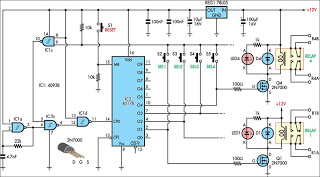
basic circuit makes rgb color organ
A color organ is an electronic device that visually represents sound through the emission of colored lights. It operates on the principle of converting audio signals into corresponding light signals, allowing the viewer to experience music in a multi-sensory manner. The core components of a color organ typically include a microphone or audio input, signal processing circuitry, and an array of lights, such as LEDs or incandescent bulbs.
The audio signal is captured by the microphone, which converts sound waves into an electrical signal. This signal is then processed using filters and amplifiers to isolate specific frequency ranges. The processed signals are subsequently used to control the intensity and color of the lights. Different frequency bands correspond to different colors or light patterns, creating a dynamic visual display that changes in real-time with the music.
The design of a color organ can vary significantly depending on the desired complexity and features. Basic models may use simple analog circuits, while more advanced versions may incorporate digital signal processing (DSP) techniques to achieve greater precision and flexibility in light modulation. Some color organs even allow for user customization, enabling users to select specific colors or patterns to correspond with particular sounds or musical styles.
In summary, a color organ serves as an innovative interface between auditory and visual experiences, harnessing the principles of wave theory to create a captivating display that enhances the enjoyment of music.The idea of a color organ is that any sound, including musical sound, can be transformed into light. As stated by wave theory, both music and light have.. 🔗 External reference
Related Circuits
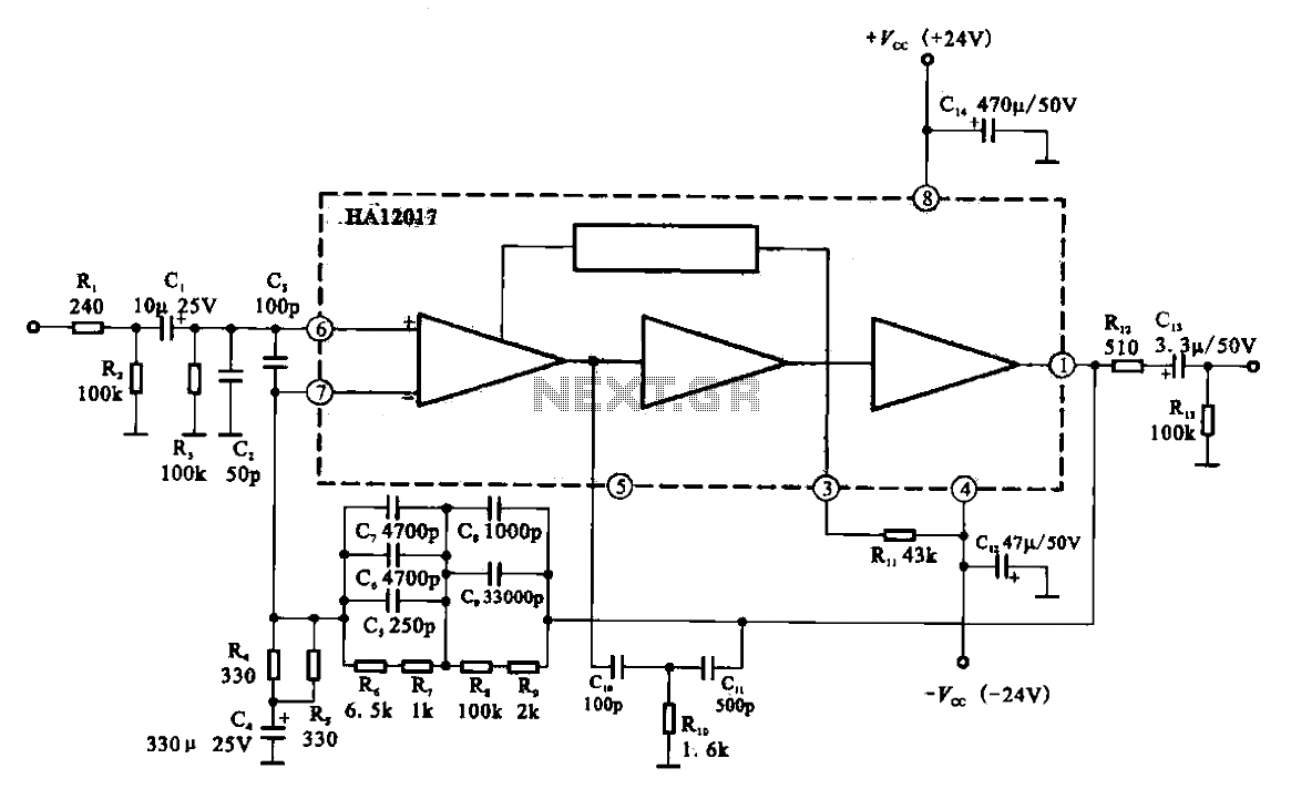
Low-noise preamplifier circuit. This circuit demonstrates a typical low-noise preamplifier design, which can be utilized to amplify signals from sources such as magnetic heads and microphones within audio applications. The input signal is coupled through a capacitor and subsequently...
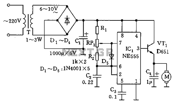
The circuit utilizes a 555 timer as the core component to create an astable multivibrator. The oscillation period T is given by the formula T = 0.693 (R1 + 2R2) C1, which corresponds to an oscillation frequency of approximately...
This circuit is designed for use in a hi-fi showroom, allowing for the selection of different speakers to connect to a stereo amplifier for comparative listening. It can also serve similar applications where only one device from a set...
The figure illustrates the 567 FM demodulator circuit. The FM signal is received at pin 3, while the demodulated output signal is available at pin 5. The central frequency of the FM signal that the circuit can demodulate is...
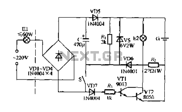
Figure 283 illustrates a blackout emergency lighting controller designed for straightforward external installation with two leads. This controller can directly replace the P Chan Tong Ge opening. Under normal power conditions, it functions like a conventional switch to control...
The circuit was designed to produce a 500mW output power transmitter whose signal is modulated by FM using four transistors. This circuit functions as a frequency modulation (FM) transmitter, capable of delivering an output power of 500 mW. The...
Warning: include(partials/cookie-banner.php): Failed to open stream: Permission denied in /var/www/html/nextgr/view-circuit.php on line 713
Warning: include(): Failed opening 'partials/cookie-banner.php' for inclusion (include_path='.:/usr/share/php') in /var/www/html/nextgr/view-circuit.php on line 713