
basic oscillator circuit using two
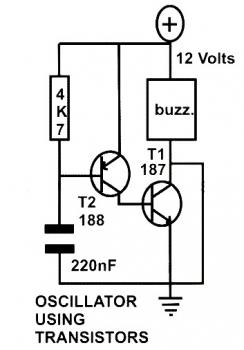
The basic oscillator circuit described operates on the principle of feedback and gain through the use of two transistors, typically arranged in a configuration that allows for the generation of square wave signals. Each transistor amplifies the signal from the other, creating a loop that sustains oscillation. The frequency of oscillation is determined by the values of the resistors and capacitors in the circuit, specifically through the RC time constant.
In practice, the use of a potentiometer instead of a fixed resistor provides an adjustable means to control the frequency, allowing for experimentation with different audio tones or LED flashing rates. The circuit's output can be connected to a speaker or buzzer, enabling it to serve as an alarm or alert mechanism. The LED can be utilized as a visual indicator, flashing at a rate determined by the circuit's frequency settings.
Creating a PCB for this oscillator circuit involves several steps. The first step is to design the schematic using PCB design software such as Eagle, which allows for the creation of a layout that can be printed. Once the design is complete, it is printed onto photo or glossy paper using a laser printer. The printed design is then aligned with the copper side of the PCB and secured in place. The application of heat from a hot iron plate transfers the toner from the paper to the PCB, creating a mask for the etching process. This method ensures that the copper traces remain intact during etching, resulting in a functional PCB that can be populated with the necessary components to complete the oscillator circuit. If access to a laser printer is limited, alternative options include printing on standard paper and utilizing a local copy service to achieve the desired glossy finish for the PCB transfer.This is the schematic diagram of basic oscillator circuit which using two transistors. When two transistors and a couple of passive components are connected as shown in the figure, the circuit starts to oscillate. The frequency of oscillation can be adjusted by changing the values of either the resistor or the capacitor.
For easier experiment, you may replace the resistor with 10K potensiometer. By increasing its frequency to a suitably high level, it can be used to drive a speaker or a buzzer to produce an audio alarm note. By sufficiently reducing its frequency, the circuit may be used to flash a LED as a warning indicator.
Make a PCB in very easy steps. ! Create your PCB design using PCB designer software like Eagle, print out your design on photo paper or glossy paper with laserjet printer. Stick the printed design on the PCB (copper side) and then heat it using hot iron plate. The ink will stick on the PCB and it will be ready for etching process. Note: If you don`t have laserjet printer, then you can print the design on standard paper. Copy the printed design at Copy Service around your location (with glossy paper). 🔗 External reference
Related Circuits
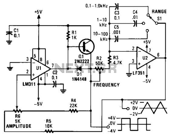
This is a simple triangle-wave generator utilizing two integrated circuit (IC) devices and a transistor. The triangle wave serves as feedback to the square-wave generator. It allows range switching across three intervals from 100 Hz to 100 kHz. Additional...

Only the R channel is shown, with the original reference PCB label. Figure (a) illustrates the front tone circuit, which consists of a common negative feedback operational amplifier in an RC circuit configuration. The microphone signal is amplified by...
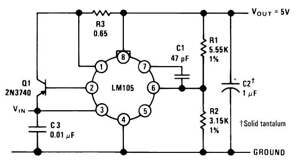
A single diffused, wide base transistor, such as the 2N3740, is recommended due to its reduced tendency to cause oscillation issues compared to double diffused, planar devices. Additionally, it exhibits greater reliability under overload conditions, and low-cost options are...
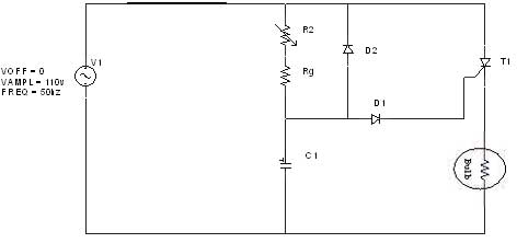
The diagram illustrates an R-C-Diode circuit that provides full half-cycle control (180 electrical degrees). During the positive half-cycle of the SCR anode voltage, the capacitor charges to the trigger point of the SCR, a process governed by the RC...
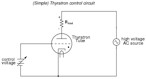
An often neglected area of study in modern electronics is that of tubes, more precisely known as vacuum tubes or electron tubes. Almost completely overshadowed by semiconductor, or "solid-state" components in most modern applications, tube technology once dominated electronic...

The circuit features grounds ISO122/124 and PGA102, with ISO150 forming a gain programmable channel isolation circuit. The input signal VIN is amplified by the instrumentation amplifier PGA102 to ISO122P, which then outputs VOUT from the isolation amplifier ISO102P. Two...
Warning: include(partials/cookie-banner.php): Failed to open stream: Permission denied in /var/www/html/nextgr/view-circuit.php on line 713
Warning: include(): Failed opening 'partials/cookie-banner.php' for inclusion (include_path='.:/usr/share/php') in /var/www/html/nextgr/view-circuit.php on line 713