
rc triggering circuit
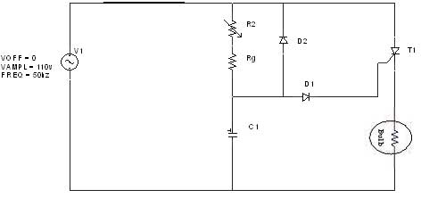
The R-C-Diode circuit operates by controlling the timing of the SCR (Silicon Controlled Rectifier) firing, which is crucial for applications requiring precise power control such as dimmers, motor speed controllers, and heaters. The capacitor in the circuit plays a pivotal role, charging during the positive half-cycle and discharging when the SCR is triggered. The RC time constant, defined by the resistor (R) and capacitor (C) values, determines how quickly the capacitor charges to the necessary threshold voltage to trigger the SCR.
During operation, as the SCR is forward-biased in the positive half-cycle, the capacitor charges up to a certain voltage level. This voltage level is dependent on the RC time constant, which is influenced by the resistance and capacitance values selected in the circuit. Once the capacitor voltage reaches the SCR's gate trigger voltage, the SCR turns on, allowing current to flow through the load.
In the negative half-cycle, diode D2 ensures that the capacitor discharges in a controlled manner, preventing reverse current flow that could damage the SCR. The capacitor's voltage can reverse as the supply voltage increases, allowing it to recharge in the opposite direction. This mechanism resets the capacitor for the next cycle, ensuring that the circuit can continuously control the load based on the input voltage waveform.
The ability to vary the firing angle from 0 to 180 degrees allows for a flexible control mechanism, enabling the adjustment of the power delivered to the load. This feature is particularly beneficial in applications where varying levels of power are required, enhancing the circuit's versatility and efficiency. Overall, the R-C-Diode circuit exemplifies a fundamental approach to phase control in AC circuits, providing effective management of power delivery through precise timing of SCR operation.Diagram shows an R-C-Diode circuit giving full half-cycle control (180 electrical degrees). On the positive half-cycle of SCR anode voltage the capacitor charges to the trigger point of the SCR in a time determined by the RC time constant and the rising anode voltage. The top plate of the capacitor charges to the peak of the negative voltage cycl e through diode D2 on the negative half-cycle, resetting it for the next charging cycle. During negative half cycle capacitor charges in reverse direction when the supply voltage increases towards positive side the capacitor voltage also recharges in opposite direction. When this capacitor voltage reaches threshold voltage SCR will turn on and capacitor discharges through diode D2 and its voltage become very small positive voltage.
Firing angle can be varied from 0 to 180 degree. 🔗 External reference
Related Circuits
A thermistor is utilized in the circuit for heat sensing, while two 5K variable resistors are incorporated to calibrate the circuit for activating the relay at the desired temperature. The inclusion of a 1N4007 diode across the relay serves...
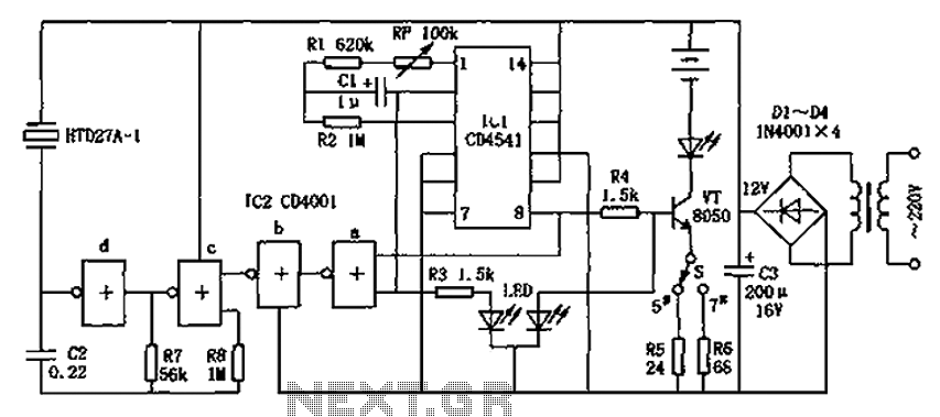
The CD4001/CD4541 nickel-cadmium battery automatic charger circuit is illustrated in the figure. This circuit is designed for charging up to seven rechargeable nickel-cadmium batteries. It features automatic charging with constant current characteristics. Once powered, the circuit activates an internal...
A device that conducts electric current and converts electrical energy into another form. Power consumed by a device or circuit while performing its function can be represented by a resistor and capacitor. The capacitor in the load circuit represents...
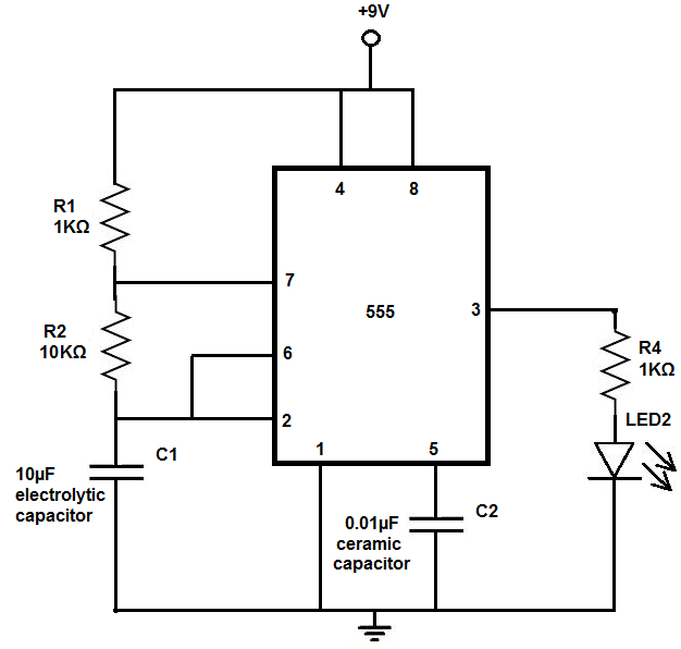
The 555 timer chip is a versatile integrated circuit (IC) that, when connected correctly, can generate pulses of current at specific intervals determined by a resistor-capacitor (RC) network. In this mode, the LED does not remain constantly lit; it...
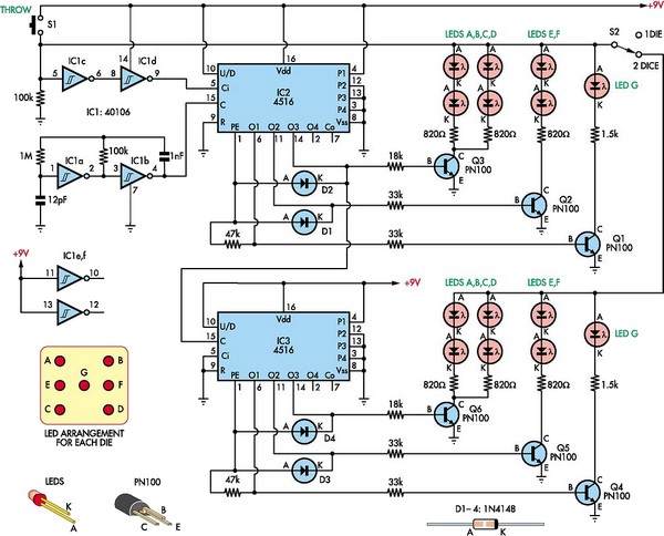
This circuit utilizes two 4516 integrated circuits (ICs) to simulate a game involving two dice. A switch is included to select whether one or two dice will be activated with each press. A 9-volt battery is sufficient for power...
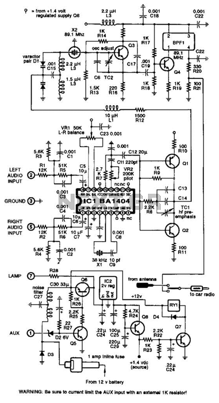
A BA1404 integrated circuit (IC) is utilized to generate a complete FM multiplex (MPX) signal. The chip incorporates all necessary circuitry. Components CI, R3, R4, and C4 are responsible for providing pre-emphasis. The transmitter operates on a single AA...
Warning: include(partials/cookie-banner.php): Failed to open stream: Permission denied in /var/www/html/nextgr/view-circuit.php on line 713
Warning: include(): Failed opening 'partials/cookie-banner.php' for inclusion (include_path='.:/usr/share/php') in /var/www/html/nextgr/view-circuit.php on line 713