Basics of Thyristors
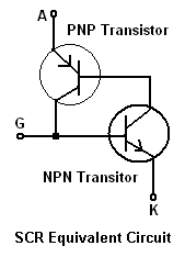
A thyristor is a switching device that operates based on the internal regenerative feedback of two transistors. One of the most common types is the silicon-controlled rectifier (SCR), which features a PNPN structure. Thyristors are highly reliable, with current ratings reaching several thousand amperes and voltage ratings up to 5000V. The unique capability of this device lies in its ability to switch hundreds of watts of load by applying only a few microwatts of pulses to the gate. A thyristor can be activated in approximately 1 microsecond and deactivated in about 15 microseconds. This rapid switching characteristic makes it suitable for various industrial control applications, where switching frequencies can reach several kilohertz. The device is turned on by applying a positive voltage to the gate relative to the cathode. When the gate voltage surpasses the threshold voltage and the current exceeds the threshold current, the device turns on, allowing load current to flow from the anode to the cathode. The equivalent circuit of the thyristor comprises two transistors, one NPN and one PNP, with the collector of the PNP connected to the base of the NPN, forming the gate. Once the SCR gate is triggered, each transistor maintains the other in the on state. The maximum reverse breakdown voltage must not be exceeded, as this could result in irreversible damage to the device. Thyristors are unilateral devices, conducting current in only one direction. Once activated, the internal resistance decreases significantly, causing the device to enter saturation. In AC control circuits, the thyristor is placed in series with the load, and a gate circuit is utilized to pulse the gate for activation. The device automatically turns off when the AC line voltage crosses zero. Load power is regulated by adjusting the conduction angle of the device. Due to its unilateral nature, only half of the AC waveform can be utilized; therefore, two thyristors can be connected in inverse parallel to create a triac, enabling control over the entire waveform.
Thyristors, particularly silicon-controlled rectifiers (SCRs), are essential components in power electronics, enabling efficient control of electrical power. Their structure, which consists of alternating layers of P-type and N-type semiconductor material, allows for effective switching capabilities under high voltage and current conditions. The regenerative feedback mechanism inherent in the SCR design ensures that once the device is turned on, it remains in a conductive state until the current through it drops below a certain threshold, known as the holding current.
In practical applications, SCRs are often employed in phase control circuits, where they can modulate the power delivered to resistive loads, such as heaters and incandescent lights. By varying the timing of the gate pulse relative to the AC waveform, the effective power can be adjusted, providing smooth control over the output. The ability to handle high power levels makes SCRs suitable for industrial applications, including motor control, light dimming, and temperature regulation.
When implementing SCRs in a circuit, careful consideration must be given to the gate drive requirements, which typically involve a dedicated circuit to generate the necessary pulse. Additionally, protection circuits are often included to guard against voltage spikes and ensure the device operates within its specified limits. The thermal management of SCRs is also critical, as excessive heat can lead to failure; therefore, proper heat sinking and thermal design are essential for reliable operation.
In summary, the thyristor's robust performance, high current and voltage ratings, and rapid switching capabilities make it a vital component in modern electrical systems, particularly in applications requiring precise control of power delivery.Thyristor is a switching device based on internal regenerative feedback of 2 transistors. One of the most popular type is called silicon controlled rectifier(SCR). They are basically a PNPN structure. They are very reliable and have current ratings up to a few thousands amperes and voltage ratings up to 5000V. The power of this device is that it i s able to switch hundreds of watts of load by just supplying a few microwatts pulses onto the Gate of the device. This device can be turned on in about 1us and turn off in about 15us. This characteristic has enabled it to solve many industrial switching control applications where the switching can go up to a few kHz.
It is turned on by making a gate positive with respect to the cathode. When the gate voltage reaches the threshold voltage and the current reaches the threshold current, the device will turn on and the load current will flow from anode to cathode. As shown in the figure above, the equivalent circuit of the thyristor consists of 2 transistors, 1 NPN and 1 PNP.
By the structure, the Collector of PNP is connected to the base of NPN and hence a Gate is formed. Once the SCR gate is triggered ON, each transistor will hold the other one ON. The characteristic is shown in the figure below. The maximum reverse breakdown voltage must not be exceeded or else the device will be damaged beyond recovery. This device is a unilateral device in that it conduct in one direction only. Once it turned on, the internal resistance will drop to a low value and caused the device to go into saturation.
In AC control circuitry, the device is in series with the load and a gate circuit is used to pulse the gate to turn it on. The turn off of the device is automatic when the AC line passes through zero. Load power is controlled by the conduction angle of the device. As it is a unilateral device, only half of the waveform can be used. In order to achieve full waveform, 2 devices are used and connected in inverse parallel and a device called triac is formed.
🔗 External reference
