
fm receiver basics
FM receivers are predominantly designed using the superheterodyne architecture, which enhances selectivity and sensitivity. This design involves mixing the incoming FM signal with a locally generated frequency to produce an intermediate frequency (IF) that can be more easily processed. The superheterodyne receiver typically consists of several key stages: RF amplification, frequency conversion, IF amplification, and demodulation.
The RF stage amplifies the incoming FM signal while filtering out unwanted frequencies. The frequency conversion stage employs a mixer, where the FM signal is combined with a local oscillator signal. The output of this stage is the IF signal, which is at a fixed frequency, allowing for consistent amplification and filtering. The IF stage further amplifies the signal and removes any remaining unwanted frequencies.
The demodulation stage is critical in FM receivers. It utilizes a discriminator or a phase-locked loop (PLL) to convert the frequency variations of the FM signal back into the original audio signal. The discriminator detects changes in frequency and translates them into corresponding amplitude changes, effectively reconstructing the audio signal for amplification and playback.
Overall, FM receivers provide improved sound quality and resistance to noise compared to AM receivers, making them a popular choice for radio broadcasting. The evolution from amplitude modulation to frequency modulation has significantly enhanced the listening experience by minimizing the impact of noise and distortion.Mainly f. m. receivers are of the superhetrodyne variety. Before we go into any depth about f. m. radio receivers let`s consider the principal differences between a. m. and f. m. signals. At first glance it might seem I am merely stating the blinding obvious but the differences are indeed quite profound. An a. m. receiver relies upon the original carrier signal (station frequency) having been amplitude modulated. This means the original amplitude (strength) varies at an audio rate. Looking at figure 1 we can see an unmodulated carrier signal as it might be seen on an oscilloscope. as you can see the amplitude of the carrier signal is unvarying, it remains constant in height looking from the top of the figure to the bottom of the figure. This carrier is common to both a. m. and f. m. signals. Perhaps the a. m. carrier signal repeats each cycle from point (a) to point (b) - "blue" - in figure 2 below at the rate of 810, 000 times a second, this represents a frequency of 810 Khz and would be in the a.
m. radio band. Here you will notice that the audio modulating signal which is depicted in red has varied the strength of the carrier signal which is depicted green for purposes of this illustration. You will note my skills as a graphic artist leave much to be desired (hint: anyone able to contribute oscillograghs in.
jpg or. gif formats ) but you should be able to see the carrier sine wave envelope is being varied in strength by the red audio signal. In the receiver circuit a diode detector can convert that envelope above back into the original audio signal for later amplification although some distortion does result.
It was to an extent this distortion property that people sought a better means of transmission. More important it was discovered that noise (either man made QRM or natural noise QRN) was amplitude in its properties. I have depicted two blue lines in the diagram above, these represent noise impulses caused perhaps by automobile ignition, nearby fluorescent lighting, your computer or atmospheric noise such as a distant storm.
Note the blue lines extend beyond the amplitude envelope, they could be many times the magnitude of the received signal. For these reasons frequency modulation evolved. Instead of varying the amplitude of the carrier signal, which remains constant, we vary the carrier frequency more or less by the audio frequency.
🔗 External reference
Related Circuits
It is important to recognize that the EC10 is a vintage receiver with collector appeal. Any modifications should aim to preserve its original state, and most of the following suggestions adhere to this principle. While replacing all Germanium transistors...
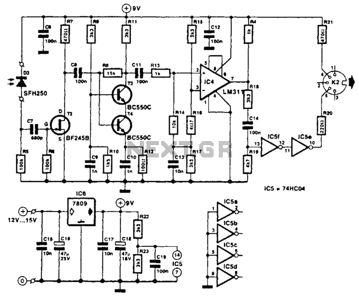
The receiver photodiode SFH250 is utilized to convert optical data pulses at a rate of 32.5 Kbps into electrical signals. The buffer T2 transmits these signals to a cascade amplifier consisting of transistors T3 and T4, followed by an...
This converter allows reception of six metre signals on a two metre receiver. It should therefore be useful for those with single or dual band sets that do not cover 50 MHz. More: To eliminate the need to obtain...
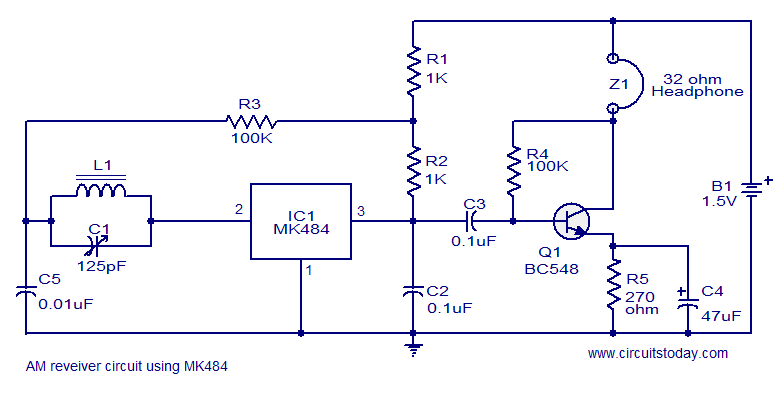
A cost-effective and straightforward AM receiver circuit utilizing the MK484 integrated circuit. The circuit requires minimal external components and operates within a frequency range of 150 kHz to 3 MHz. The MK484 AM receiver circuit is designed for simplicity and...
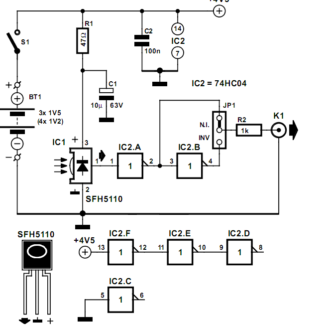
Many audio systems consist of separate units, and due to economic reasons, only the amplifier is equipped with a remote control receiver module. In audio system designs where components are split into separate units, it is common for only the...
Wireless headphone transmitter and receiver systems are now widely available in the market, offering a variety of pricing options along with reliable technical specifications for various applications. These include wireless headphones for televisions, computers, and earbuds. A wireless headphone...
Warning: include(partials/cookie-banner.php): Failed to open stream: Permission denied in /var/www/html/nextgr/view-circuit.php on line 713
Warning: include(): Failed opening 'partials/cookie-banner.php' for inclusion (include_path='.:/usr/share/php') in /var/www/html/nextgr/view-circuit.php on line 713