
Bathroom Deoderizer Control

The circuit design incorporates a DC motor, which serves as the fan, ensuring effective dispersion of the deodorant. The motor is connected to a power source, specifically a D cell battery, providing the necessary voltage and current for operation. The photocell, or light-dependent resistor (LDR), is strategically placed to monitor ambient light levels. When the light intensity falls below a predetermined threshold, the photocell sends a signal to a transistor or relay that interrupts the power supply to the motor, effectively turning off the fan and conserving battery life.
An LED is included in the circuit as an indicator for battery status. This LED is connected in parallel with a resistor to limit current and prevent damage. When the circuit is powered, the LED will flash if the battery voltage is above a certain level, indicating that the battery is in good condition. If the battery voltage drops below this level, the LED will not flash, serving as a visual cue for the need to replace the battery.
The overall schematic may include additional components such as capacitors for smoothing out voltage fluctuations, and diodes for reverse polarity protection, ensuring the reliability and longevity of the device. The integration of these components allows for efficient operation while maintaining user safety and convenience.This is the type that has a little DC motor fan positioned above a small container containing a deoderant liquid or jelly, and runs off a D cell. The photocell turns off the fan when it gets dark. The LED flashes if the battery is good. 🔗 External reference
Related Circuits
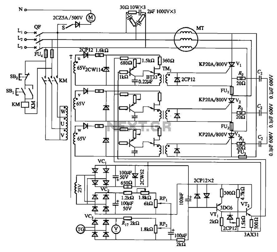
The circuit depicted in Figure 3-181 comprises three thyristors, labeled V1 to V3. The trigger circuit utilizes a single-junction transistor relaxation oscillator. The speed control circuit incorporates negative feedback. A master adjust potentiometer, designated as RPi, is used to...
PWM is a device that can be utilized as an efficient light dimmer or DC motor speed controller. Function: for a general-purpose device that can... PWM (Pulse Width Modulation) is a versatile technique widely employed in various electronic applications, particularly...
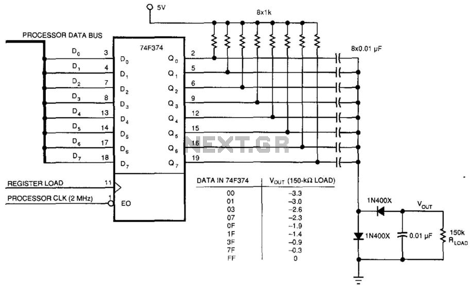
This circuit was used to produce a variable negative voltage for contrast control of an LCD display. A 74F374 generates a square wave that is AC coupled to a rectifier and load. By using the microprocessor clock and data...
This shows the overall circuit diagram of the power control unit. On the left, there is a main relay controlled by the key switch. The power control unit circuit diagram illustrates the fundamental components and their interconnections, providing a clear...
A schematic diagram for the remote analyzer is presented. The circuit operates from a basic 5-V power supply, which includes components PL1, S1, T1, a bridge rectifier made up of diodes D1 through D4, capacitor C1, and a common...
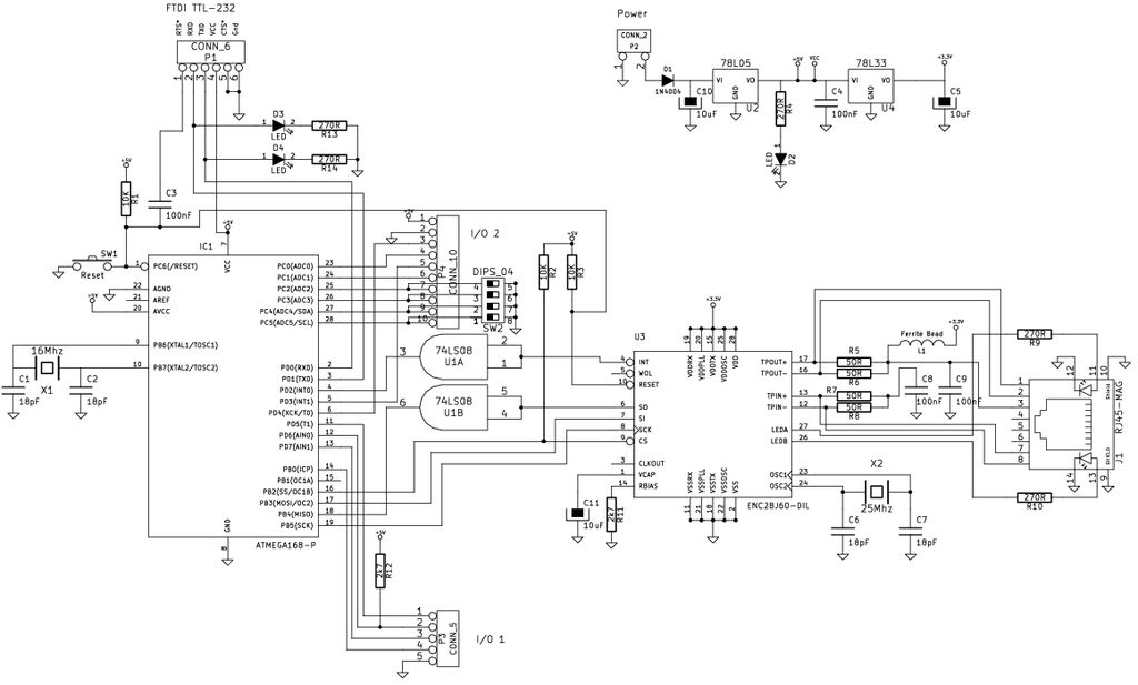
The Arduino is a simple and accessible controller platform suitable for various projects. A few months ago, an Ethernet shield was purchased for it. The Arduino platform is widely recognized for its user-friendly interface and versatility, making it a popular...