
Thyristor AC torque motor speed control circuit 2

The circuit operates by utilizing the three thyristors (V1, V2, and V3) to control the power delivered to a motor. Thyristors are semiconductor devices that function as switches, allowing current to flow when triggered by a gate signal. In this configuration, they are arranged to manage the motor's speed effectively.
The single-junction transistor relaxation oscillator serves as the triggering mechanism for the thyristors. This oscillator generates a periodic signal, which is crucial for initiating the conduction of the thyristors. The frequency and duty cycle of this signal can be adjusted based on the desired motor speed.
Incorporating negative feedback in the speed control circuit allows for improved stability and accuracy in maintaining the motor's speed. This feedback mechanism continuously monitors the motor's performance and adjusts the triggering signal accordingly, ensuring that any variations in speed are corrected in real-time.
The master adjust potentiometer (RPi) plays a critical role in fine-tuning the system. By varying the resistance, the potentiometer alters the voltage level at the input of the trigger circuit, which in turn modifies the firing angle of the thyristors. This adjustment allows for precise control over the torque output of the motor, enabling it to respond effectively to varying load conditions.
Overall, this circuit design is well-suited for applications requiring adjustable motor speed and torque control, leveraging the advantages of thyristors and feedback mechanisms for enhanced performance. Circuit shown in Figure 3-181. Main circuit consists of three thyristor Vi-V3 components. Trigger circuit single-junction transistor relaxation oscillator. Speed circuit has ne gative feedback. Master adjust potentiometer RPi, can change the torque of the motor speed.
Related Circuits

Illuminate your tabletop with this stylish White LED Lamp. It is powered through a USB port, making it perfect for taking notes while browsing the internet. The USB port can provide a convenient power source. The White LED Lamp is...
This remote telephone bell ringer enables the use of a large and loud external bell instead of or in addition to the built-in ringer found in most modern telephones. It is particularly suitable for large outdoor areas, noisy shops,...
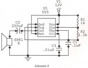
This circuit features an astable oscillator constructed around a 555 timer, generating an alarm tone of 1.8 kHz, which directly drives a speaker. It serves as a fundamental alarm circuit that can be utilized in various projects. Although the...
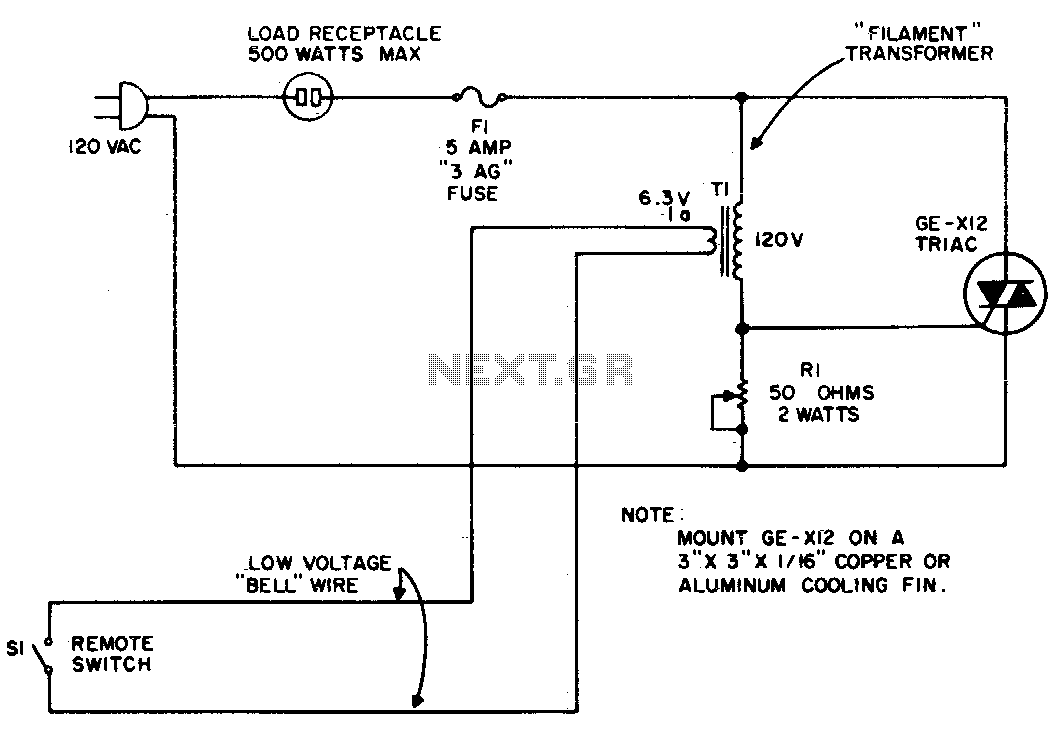
The circuit utilizes the primary current of a small 6-volt filament transformer to control a triac and activate the load. When switch S1 in the 6-volt secondary of the transformer is open, a small "magnetizing" current flows through the...
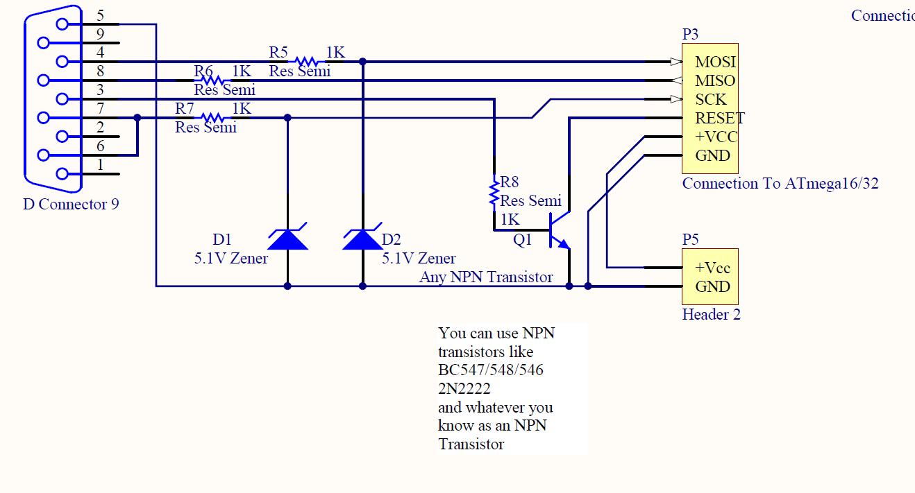
ISP programmer with circuit diagram for AVR Atmega32 microcontroller. This ISP burner circuit is an adaptation of the Pony programmer and uses PonyProg software. The ISP (In-System Programming) programmer designed for the AVR Atmega32 microcontroller facilitates the programming of the...

The HF/SW receiver preamplifier consists of a broadband toroidal transformer (LI-a and Ll-b), an LC network featuring a 1600-kHz high-pass filter and a 32-MHz low-pass filter, inductors L2 and L3 (26 turns of #26 enameled wire wound on an...