
Up-Controlled Negative Voltage Converter
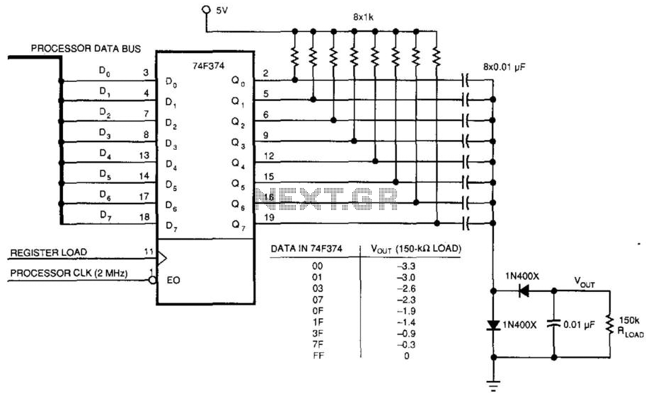
This circuit employs a 74F374 flip-flop to generate a square wave output, which serves as the primary signal for creating a variable negative voltage. The flip-flop's output is AC coupled to a rectifier circuit, which converts the AC signal into a DC voltage. The rectifier typically consists of diodes arranged in a configuration that allows for the effective conversion of the square wave into a usable DC level, which can be further smoothed using capacitors to reduce ripple.
The microprocessor (uP) plays a crucial role in this circuit by providing the clock signal necessary for the flip-flop operation. Additionally, data from the processor bus is utilized to control the timing and loading of the flip-flop, allowing for precise adjustments to the output voltage level. The load signal from the microprocessor enables the system to dictate when the flip-flop should latch the input data, effectively controlling the duty cycle of the square wave output and consequently the average DC voltage produced.
To achieve variable contrast control for the LCD display, the circuit can be designed with feedback mechanisms that monitor the output voltage level. This feedback can be processed by the microprocessor to adjust the load signal dynamically, ensuring that the desired contrast level is maintained across varying conditions and display requirements. Components such as operational amplifiers may also be incorporated to further refine the output voltage characteristics, ensuring stability and responsiveness to user inputs or system changes.
Overall, this circuit provides an efficient method for generating a variable negative voltage, enhancing the functionality and user experience of LCD displays through effective contrast control. This circuit was used to produce a variable negative voltage for contrast control of an LCD displa y. A 74F374 generates a square wave that is ac coupled to a rectifier and load. By using the uP clock and data from the processor bus, and properly timed load signal, the dc level generated can be controlled by the uP. 🔗 External reference
Related Circuits
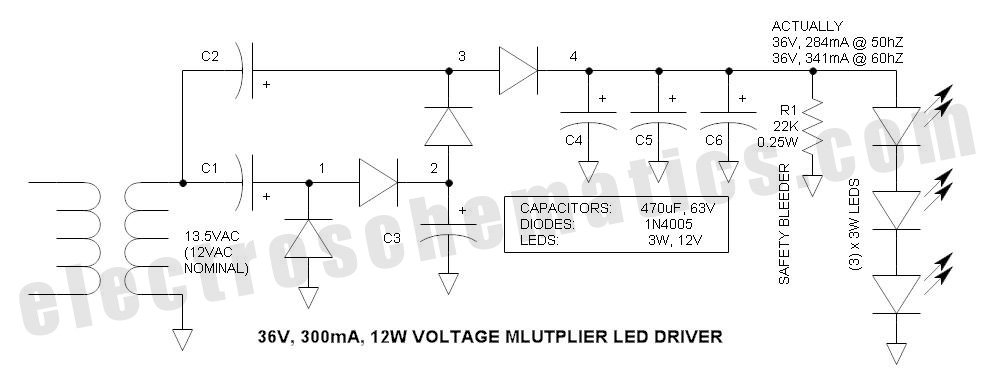
This power supply circuit is designed around a standard 12VAC landscape lighting transformer. The availability and selection of transformers have long posed challenges for experimenters, often leading them to use potentially hazardous off-line capacitor-limited power supplies. However, the widely...

This circuit represents a negative resistance configuration. All previous circuits utilize RC time constants to achieve resonance. LC combinations can also be employed, providing good frequency stability, high Q factor, and rapid startup. In this circuit, a signal input...
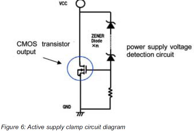
This article presents a high reliability 1200V High Voltage Integrated Circuit (1200V HVIC) for half bridge driver applications, aimed at reducing the IC's supply current by approximately 50%. The 1200V High Voltage Integrated Circuit (HVIC) is designed specifically for half-bridge...
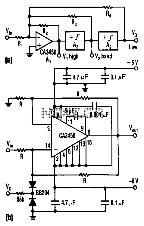
The control voltage Vc effectively adjusts the cutoff frequency w0 of this state-variable filter to any desired value, ranging from approximately 1.7 MHz to 5 MHz, using a BB 204 varicap and a resistance of 100 kΩ. Vc can...
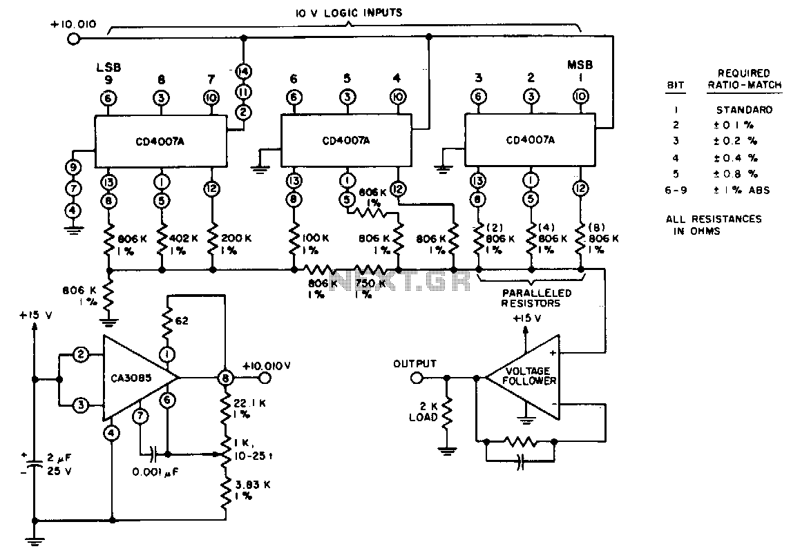
Three CD4007 A integrated circuit packages perform the switching function using a 10-V logic level. A single 15-V supply provides a positive bus for the follower amplifier and powers the CA3085 voltage regulator. The scale adjustment function is facilitated...
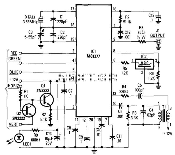
This circuit utilizes a Motorola MC1377 to generate NTSC video from an RGB source. The components are not critical, with the exception of resistor R7, which should have a tolerance of 1%, and capacitor CB, which should have a...