
Power Control Unit
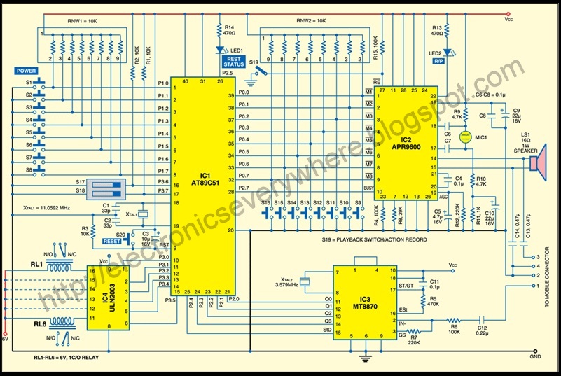
The power control unit circuit diagram illustrates the fundamental components and their interconnections, providing a clear overview of the functionality and operation of the system. The main relay, positioned on the left side of the diagram, acts as a pivotal element in the circuit, serving to control the flow of power through the system. It is activated by the key switch, which functions as an input device allowing the user to initiate or terminate power delivery.
In a typical configuration, when the key switch is turned to the 'on' position, it completes the circuit, allowing current to flow to the relay coil. This energizes the relay, causing it to close its contacts and connect the power source to the load, thereby supplying power to the intended devices or circuits. The relay's contacts are rated for the specific voltage and current levels of the application, ensuring safe and efficient operation.
In addition to the main relay and key switch, the circuit may include additional protective elements such as fuses or circuit breakers to prevent overload conditions. These components are critical for safeguarding the entire system from potential damage due to excessive current or short circuits.
Furthermore, the circuit diagram may also depict various indicators, such as LED status lights, which provide visual feedback on the operational state of the power control unit. These indicators enhance user interaction by signaling whether the system is powered on or off, and they can be integrated in parallel with the relay contacts.
Overall, the power control unit circuit diagram serves as an essential reference for understanding the design, operation, and safety features of the system, facilitating troubleshooting and maintenance activities.This a shows the overall circuit diagram of the power control unit. On the left, there is a main relais controlled by the key switch and the . 🔗 External reference
Related Circuits
A circuit that allows for the operation of home appliances such as lights and water pumps from a remote location, such as an office. This system enables users to turn off appliances with their cellphones if they forget to...
Another adjustment of application operational amplifiers to adapt a power supply is apparent below. The power supply requires an additional adjustment to supply the op-amps with a bipolar voltage (+/- 8 volts), and the negative voltage is also used...
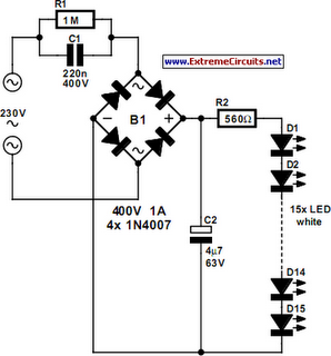
An array of white LEDs can serve as a small lamp for the living room. LED lamps are readily available, resembling standard halogen lamps, and can be installed in a standard 230-V light fixture. A capacitor is employed to...
A switch that is controlled by its ambient temperature operates without human intervention, except during the assembly of the electronic thermostat. This thermally controlled switch has numerous practical applications. For instance, if the internal temperature of a computer rises...
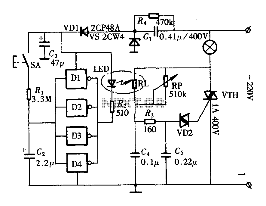
The lighting controller depicted in the figure features a gradual dimming function that prevents sudden brightness changes, which can irritate the human eye and potentially cause damage due to inrush currents. The circuit design includes a six-stage CD4069 inverter...
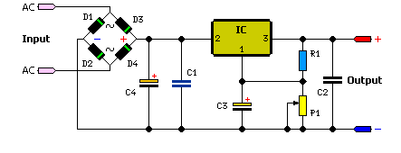
The simple method to power your projects is illustrated in the circuit diagram of a regulated power supply. This compact power supply delivers a stable voltage. This regulated power supply circuit is designed to convert an unregulated input voltage into...
Warning: include(partials/cookie-banner.php): Failed to open stream: Permission denied in /var/www/html/nextgr/view-circuit.php on line 713
Warning: include(): Failed opening 'partials/cookie-banner.php' for inclusion (include_path='.:/usr/share/php') in /var/www/html/nextgr/view-circuit.php on line 713