
figureyaga - lead acid battery charger circuit schematic
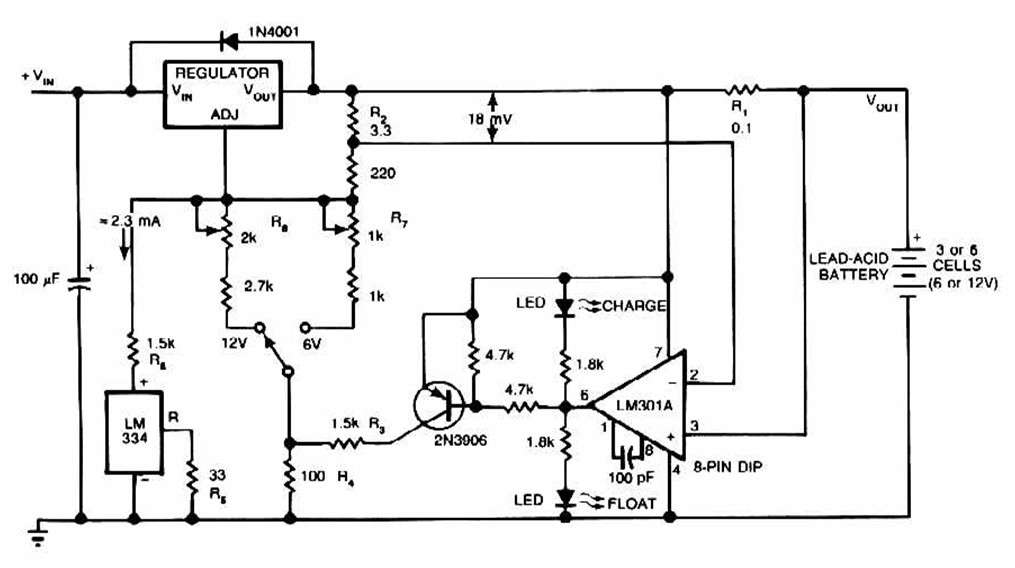
The circuit diagram illustrates the use of the LM317 integrated circuit, which can be configured to create a bridge power supply for charging a 12-volt lead-acid battery with high accuracy. This design is particularly suitable for applications requiring constant charging. Additionally, it is important to ensure proper voltage regulation and protection mechanisms are in place to prevent overcharging, which can damage the battery.
The schematic may include components such as diodes for rectification, capacitors for filtering, and resistors to set the charging current. The use of a microcontroller or additional monitoring circuits can enhance the functionality, allowing for intelligent battery management and maintenance charging. This ensures the longevity and efficiency of the battery while providing a reliable power source for various applications.
Overall, the design emphasizes the critical nature of charging rechargeable batteries, necessitating careful consideration of the circuit configuration and component selection to achieve optimal performance and safety.The schematic for this charger is pretty simple. GellCell Battery Charger: circuit to charge a Gell Cell or other lead-acid type. This simple battery level monitor circuit can indicate the charging process in 12 Volt Lead Acid battery or Tubular. 12V battery level monitor circuit schematic. Sep 24, 2009. Solar charge r for lead-acid batteries This circuit is intended for charging sealed. Solar sun tracker Cadmium Sulfide Relay Tracker Schematic. Mar 1, 2013. The usual disclaimer: The procedures and schematics on this page work fine for me, but. Testing a lead-acid battery: Voltage | Acid density | Capacity | Impedance. Improving a simple battery charger: Design goals | Circuit. automatic lead acid battery charger - Help me with protection and voltage regulation. help - lead acid charger schematic with maintenance charging - Intelligent battery charger. circuit diagrum for Battery charger 24Volt(2x12V 7Ah Batteri. Mar 6, 2013. Circuit Schematic Diagram. Charging any type of chargeable battery can be critical and involves some attention to be paid. The circuit diagram presented here shows how the IC LM317 ca be configured using just a. bridge power supply for charging a 12 volt lead acid battery with utmost accuracy. Mar 3, 2013. Lead Acid Battery Charger #1. Schematic. gif. Except for use as a normal Battery Charger, this circuit is perfect to `constant-charge`. 🔗 External reference
Related Circuits
The buba oscillator initially failed to oscillate. The first step is to check the fundamental components, as minor errors in the values of capacitors, resistors, and inductors can significantly impact performance. It is advisable to measure component values with...
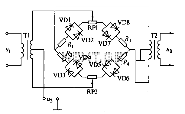
An AM diode ring circuit consists of four diodes arranged in a ring configuration, commonly referred to as a diode ring modulator circuit. This circuit offers significant advantages due to the characteristics of the diodes and the use of...
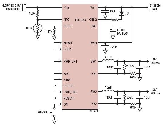
This micropower multifunction power management integrated circuit (PMIC) is designed using the LTC3554, manufactured by Linear Technology Corporation. It serves as a solution for portable Li-Ion Polymer battery-based applications. The LTC3554 integrates a USB-compatible linear PowerPath manager, a standalone...
The cell phone shield circuit employs two NE555 timer integrated circuits (ICs): one configured as a simple astable multivibrator (IC2) and the second as a monostable multivibrator (IC3). The astable multivibrator utilizes timing resistors R1 and R2 but does...
This unit would be mounted in a small plastic or preferably metal box, with a 9V battery, level control, a male XLR connector (same as on a mic) and a switch. Current drain is low, since the circuit only...
This circuit is similar to the previous one but employs positive feedback to enhance the amplitude delivered to the speaker. It was adapted from a small five-transistor radio that utilizes a 25-ohm speaker. In the prior circuit, the load...