
Simple NiCd Battery Charger

The circuit design for this NiCd charger is straightforward, providing a reliable method for charging nickel-cadmium batteries. The use of the LM317 or 78xx voltage regulator enables precise control over the output voltage and current, ensuring safe charging of the cells. The current limiting feature, implemented with resistor R3 and transistor T1, is crucial to prevent overcharging and potential damage to the cells. The LED indicator serves as a visual cue for the user, signaling the charging status and preventing user errors during operation.
The voltage divider formed by resistors R1 and R2 is essential for setting the reference voltage of the regulator. The careful selection of these resistors allows for fine-tuning the charging parameters, maintaining optimal performance across different battery configurations. The ability to adjust R1 based on the regulator's current characteristics ensures adaptability to various charging scenarios.
In applications where space and component availability are limited, this charger design stands out due to its simplicity and effectiveness. The option to omit the storage capacitor allows for flexibility in charging methods, accommodating different user requirements, such as pulsed charging for higher current applications. Overall, this NiCd charger circuit offers a practical solution for battery charging needs, combining efficiency and functionality in a compact design.A simple NiCd charger can be built using junk box` components and an inexpensive LM317 or 78xx voltage regulator. Using a current limiter composed of R3 and a transistor, it can charge as many cells as desired until a fully charged` voltage determined by the voltage regulator is reached, and it indicates whether it is charging or has reached the f
ully charged state. If the storage capacitor (C1) is omitted, pulsed charging takes place. In this mode, a higher charging current can be used, with all of the control characteristics remaining the same. The operation of the circuit is quite simple. If the cells are not fully charged, a charging current flows freely from the voltage regulator, although it is limited by resistor R3 and transistor T1.
The limit is set by the formula Imax ‰ (0. 6 V) G· R3 For Imax = 200 mA, this yields R3 = 3 . The LED is on if current limiting is active, which also means that the cells are not yet fully charged. The potential on the reference lead of the voltage regulator is raised by approximately 2. 9 V due to the voltage across the LED. This leads to a requirement for a certain minimum number of cells. For an LM317, the voltage between the reference lead and the output is 1. 25 V, which means at least three cells must be charged (3 G— 1. 45 V > 2. 9 V + 1. 25 V). For a 78xx with a voltage drop of around 3 V (plus 2. 9 V), the minimum number is four cells. When the cells are almost fully charged, the current gradually drops, so the current limiter becomes inactive and the LED goes out.
In this state, the voltage on the reference lead of the regulator depends only on voltage divider R1/R2. For a 7805 regulator, the value of R2 is selected such that the current through it is 6 mA. Together with the current through the regulator (around 4 mA), this yields a current of around 10 mA through R1.
If the voltage across R1 is 4 V (9 V 5 V), this yields a value of 390 . The end-of-charge voltage can thus be set to approximately 8. 9 V. As the current through the regulator depends on the device manufacturer and the load, the value of R1 must be adjusted as necessary. The value of the storage capacitor must be matched to the selected charging current. As already mentioned, it can also be omitted for pulse charging. 🔗 External reference
Related Circuits
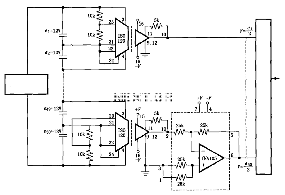
The circuit utilizes the ISO120 and INA105 instrumentation amplifiers to create a battery monitoring system for a 600V battery setup composed of 50 series-connected 12V batteries. This circuit is designed to detect charging and discharging conditions to prevent overcharging...
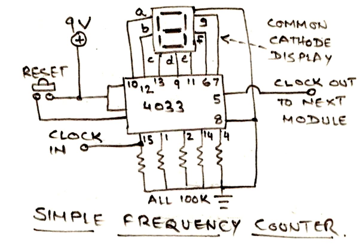
The circuit illustrated below is designed for measuring frequency in Hertz (Hz). It is straightforward to construct, utilizing a single IC 4033 and a common cathode display as the main components. For measuring higher frequencies, typically in the range...
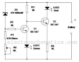
This circuit monitors the charging process of a 12 Volt Lead Acid or Tubular battery. The LED status indicates whether the battery is charging and signals when it reaches a full charge. It can be integrated into various battery...
Controlling household electrical gadgets or any electrical equipment remotely can be enjoyable. While using a remote to control devices like a TV or DVD player is a common experience, managing other domestic appliances such as water pumps and lights...
The presentation of a general power thyristor trigger circuit is more complex, and some components are difficult to procure. A successful trigger circuit has been constructed for only a few dollars. This circuit is designed to trigger a thyristor...
%2BCircuit%2Bdiagram%2Busing%2BCD4047%2Band%2BIRFZ44%2Bpower%2BMOSFET.png)
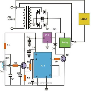
This simple low-power DC to AC inverter circuit converts 12V DC to either 230V or 110V AC. By making simple modifications, it is also possible to convert 6V DC to 230V AC or 110V AC. This inverter can be...