
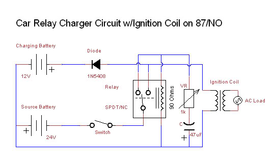
Battery charger
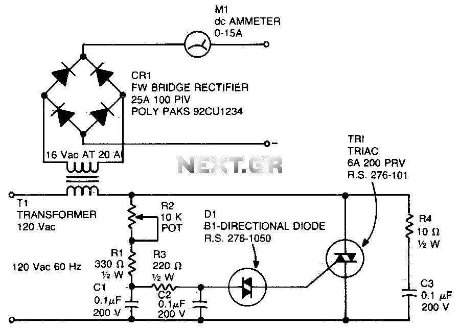
The described circuit employs a diac in conjunction with a triac to control power delivery in AC applications. The diac functions as a switching device that allows current to flow only after a specific voltage threshold is reached, effectively controlling the gate of the triac. R1 is crucial as it determines the firing threshold of the triac; once the voltage across R1 exceeds this threshold, the diac conducts, triggering the triac and allowing current to flow through the load.
C3 and R4 are integral components of the transient suppression network, designed to protect the circuit from voltage spikes that may occur during operation. C3 acts as a filter capacitor, smoothing out any rapid changes in voltage and preventing unwanted triggering of the triac. R4 serves to limit the maximum charging current to C3, ensuring that the capacitor charges within safe limits and preventing damage to the circuit.
The phase-shift network composed of R1, R2, R3, C1, and C2 is essential for controlling the timing of the triac's firing. This network introduces a phase shift in the input signal, allowing for precise control over the power delivered to the load. The values of R2, R3, C1, and C2 can be adjusted to modify the phase angle, thus influencing the timing of when the triac is triggered during each AC cycle.
Overall, this circuit configuration is commonly found in light dimmers, motor speed controls, and other applications requiring phase control of AC loads. The combination of the diac and triac, along with the supporting components, enables efficient and reliable control of power in various electronic applications.A diac is used in the gate circuit to provide work for the signal being applied to the gate. R1 a threshold level for firing the triac. C3 and R4 is selected to limit the maximum charging cur-provide a transient suppression network Rl, rent at fullTotation of R2. R2, R3, Cl, and C2 provide a phase-shift net-. 🔗 External reference
Related Circuits
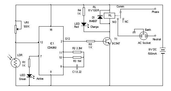
Timer for Charger Circuit Diagram. This timer circuit assists in maintaining the battery in optimal condition by enabling automatic charging for 5 to 6 hours daily, allowing the device to be left unattended. The timer circuit for the charger is...
While traveling, charging a mobile phone can be a significant challenge due to the general inaccessibility of power supply sources, leading to the risk of the battery depleting. To address the issue of mobile phone battery depletion during travel, a...
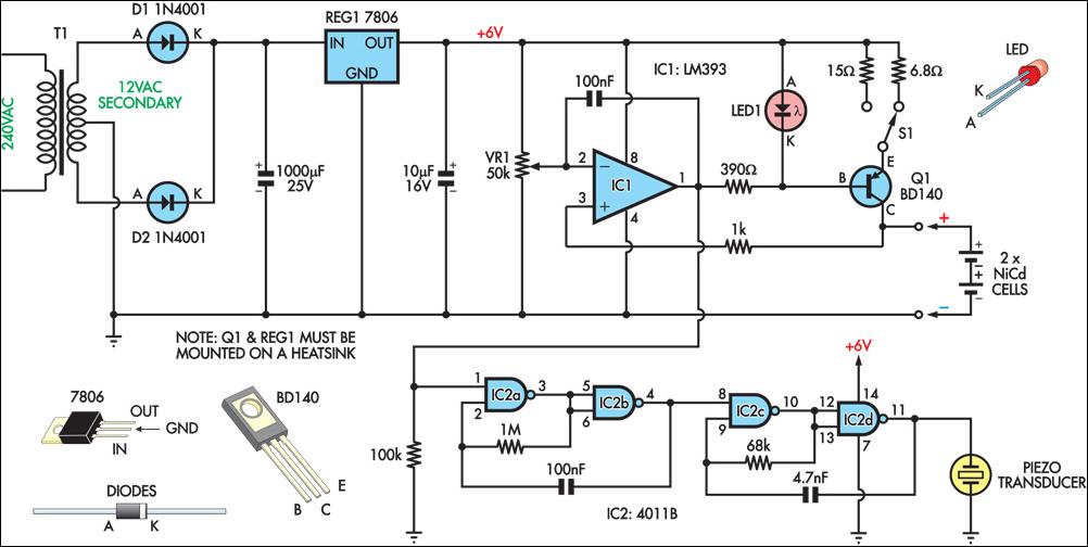
This circuit charges two NiCad cells with a constant current and features dual charging rates, voltage cutoff, and an audible alarm. The circuit is powered by a 12VAC center-tapped mains transformer, along with two rectifier diodes (D1 & D2)...
It can safely charge a 7-cell RC2000 pack in about 14 minutes, and an RC2400 or CP2400SCR pack in about 17 minutes. As a NiCd cell is being charged, two things happen which affect its temperature. Due to resistive...
A new member has joined the forum and is seeking assistance with electronics, particularly from a technical engineering perspective, although they have some experience with circuits and schematics. The individual is likely looking to enhance their understanding of electronic components,...

Bipolar +/- 15V and 5V from car battery supply power supply. Refer to the specified page for an explanation of the related circuit diagram. The described power supply circuit is designed to provide bipolar voltage outputs of +/- 15V and...