
Timer for Charger
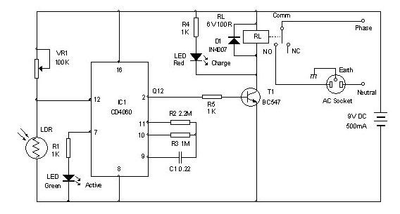
The timer circuit for the charger is designed to automate the charging process of a battery, ensuring that it remains in peak condition without requiring constant supervision. This circuit typically incorporates a timer IC, such as the 555 timer, which can be configured in monostable or astable mode depending on the desired functionality.
In a typical configuration, the timer can be set to initiate the charging cycle for a predetermined duration, usually between 5 to 6 hours. This is achieved by adjusting the resistor and capacitor values connected to the timer IC, which determine the time delay. Upon activation, the timer switches on a relay or a transistor, which in turn connects the battery to the charger.
The circuit may also include additional components such as diodes for protection against reverse polarity, capacitors for filtering, and resistors to limit current. A voltage regulator can be integrated to ensure that the battery is charged at a safe voltage level, preventing overcharging which can damage the battery.
Furthermore, an LED indicator can be added to signal the status of the charging process, providing visual feedback to the user. This timer circuit is particularly useful in applications where batteries are charged in remote locations or where user intervention is not feasible, thus enhancing the reliability and longevity of the battery system.
Overall, the timer for the charger circuit diagram exemplifies a practical solution for automated battery management, contributing to the efficiency and convenience of battery-operated devices.Timer for Charger Circuit Diagram. This timer circuit helps to keep the battery in top condition through automatic charging for 5 to 6 hours daily so that the instrument can be left unattended 🔗 External reference
Related Circuits

The following circuit illustrates the Bedside Lamp Timer Circuit utilizing the CD4060 integrated circuit (IC). It operates for 30 minutes, with a blinking LED indicating the last 6 minutes of operation. The Bedside Lamp Timer Circuit is designed to provide...
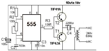
12V power inverter circuit utilizing a 555 timer for an electronic project. The 12V power inverter circuit is designed to convert a DC voltage of 12 volts into an AC voltage suitable for powering small electronic devices. The core component...
This circuit was developed in response to requests from visitors of this website for a timer that can emit a beep after one, two, three minutes, and so on, for jogging purposes. As illustrated in the circuit diagram, SW1...
If you use different batteries with actual capacity, with different self-discharge rate of batteries from different manufacturers, you will perhaps throw further described charger. Because each cell can be discharged separately recharge, can be charged with varying articles carrying...
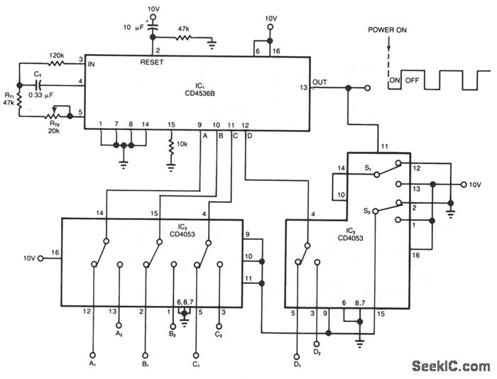
The timer circuit provides independent control of the output's on and off intervals, which can range from 0.055 seconds to 30 minutes, with minimal impact from power-line transients. IC1 is a CMOS programmable timer chip that features 24 ripple-binary...
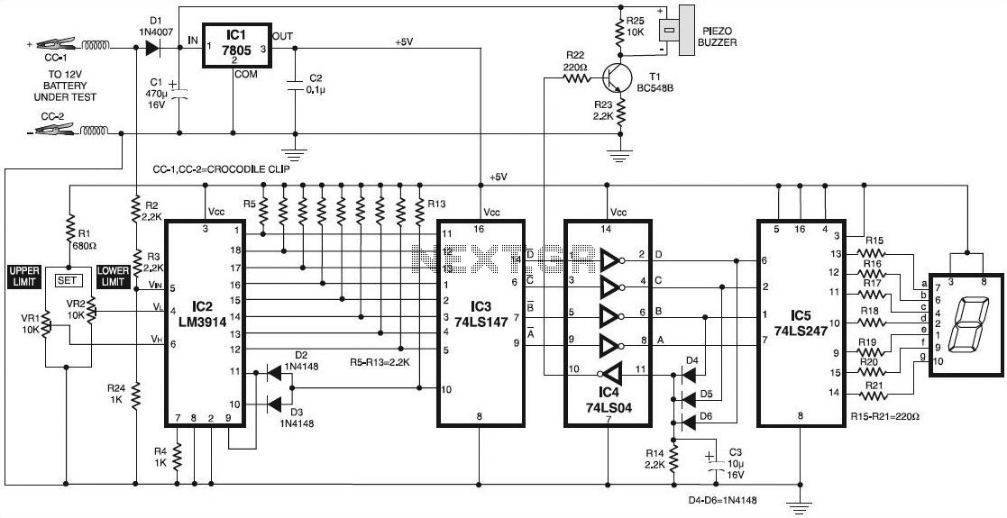
According to the manufacturer's data sheets, a 12V rechargeable lead-acid battery should be operated within a voltage range of 10.1V to 13.8V. Charging the battery above 13.8V can lead to potential damage. Lead-acid batteries are commonly used in various applications...
Warning: include(partials/cookie-banner.php): Failed to open stream: Permission denied in /var/www/html/nextgr/view-circuit.php on line 713
Warning: include(): Failed opening 'partials/cookie-banner.php' for inclusion (include_path='.:/usr/share/php') in /var/www/html/nextgr/view-circuit.php on line 713