
Nicad Charger Uses Voltage Cut-Out

This circuit is designed to efficiently manage the charging of two NiCad cells, ensuring safety and reliability through its various features. The power supply section begins with a 12VAC center-tapped transformer, which provides the necessary voltage for rectification. The rectifier diodes D1 and D2 convert the AC voltage to DC, while the 1000μF filter capacitor smooths the output, providing a stable voltage to the subsequent stages of the circuit.
The 7806 voltage regulator maintains a consistent 6V output, which is crucial for the operation of the constant-current source formed by Q1 and LED1. The choice of a red LED allows for a clear visual indication of the circuit's operation, while the transistor Q1 serves as a key component in regulating the charging current based on the selected resistance values.
The dual charging rates are achieved through the use of the emitter resistors, which are selected via switch S1. This flexibility allows for different charging times depending on the user's needs, with the circuit capable of charging standard 600mAh NiCad "AA" batteries in either 14 hours or 5 hours.
The voltage cutoff mechanism, implemented using the LM393 comparator, ensures that the batteries are not overcharged, which can lead to reduced lifespan or damage. The use of a trimpot for setting the reference voltage allows for fine-tuning based on specific battery characteristics, while the feedback capacitor stabilizes the operation and prevents oscillations around the cutoff threshold.
The inclusion of oscillators constructed from NAND gates adds an audible alert feature, enhancing user awareness of the charging process. The piezo transducer emits a tone that signals when charging is complete, providing a practical notification system.
Overall, this circuit exemplifies a well-thought-out design that prioritizes both functionality and safety in charging NiCad batteries, with careful consideration given to the charging rates, voltage monitoring, and user feedback.This circuit charges two NiCad cells with a constant current and features dual charging rates, voltage cutoff and an audible alarm. The circuit is powered by a 12VAC centre-tapped mains transformer, together with two rectifier diodes (D1 & D2) and a 1000mF filter capacitor.
A 7806 3-terminal regulator is used to generate a 6V rail for the remainde r of the circuit. Transistor Q1 and LED1 constitute a basic constant-current source. The forward voltage of the red LED (about 1. 5V) minus Q1`s base-emitter voltage (about 0. 6V) appears across the 6. 8W or 15W emitter resistors, depending on the position of S1. With a 15W resistance in the emitter circuit, the charging current is about 60mA, whereas with 6. 8W it is about 130mA. This is sufficient to charge 600mAH "AA" cells in 14 hours and five hours, respectively. An LM393 voltage comparator (IC1) is used for the voltage cutoff function. Its inverting input is set to 2. 9V (nominal) via trimpot VR1, while the non-inverting input senses battery voltage. This means that while the cells are being charged, the output transistor (in the LM393) is switched on, also switching on Q1 and enabling the current source. Once the cells are charged to approximately 80% or more of capacity, their terminal voltages will exceed 1.
45V, so the voltage at the non-inverting input (pin 3) of IC1 will exceed the reference voltage on the inverting input (pin 2). This causes IC1`s output to switch off, in turn switching Q1 off and disabling the current source. To prevent rapid switching action around the voltage cutoff point, a 100nF capacitor provides feedback between the output and inverting input of the comparator.
Four NAND gates are used to build two simple oscillators of different frequencies. When cascaded together, the result is a pulsed tone from the piezo transducer to indicate charge completion. Absolute terminal voltage is not always a reliable indicator of Nicad battery charge state. Importantly, batteries should never be charged for longer than the manufacturer`s specified period. 🔗 External reference
Related Circuits
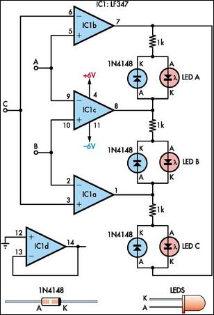
This circuit indicates which of three voltages, ranging from approximately -4V to +4V at points A, B, and C, is the highest by illuminating one of three indicator LEDs. It can also be configured to indicate the lowest of...
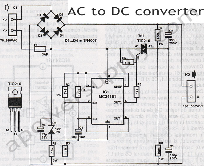
A straightforward method for charging a battery using a higher voltage source is illustrated in the accompanying circuit diagram. The circuit requires only one resistor to establish the desired charging current, which can be determined by dividing the voltage...
This voltage-to-frequency converter circuit features a voltage-controlled oscillator with a deviation of 0.5%. The integrated circuit IC1 functions as a multivibrator, generating rectangular impulses of equal width. The output frequency is adjustable via the U1 voltage. The D3 diode...
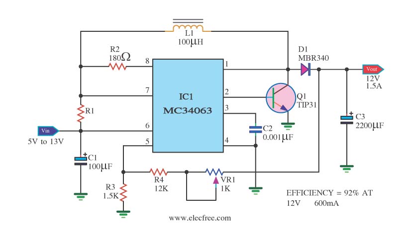
The circuit is a battery-powered voltage regulator that outputs 12V at 1.5A. It accepts an input voltage range from 5V to 13V. The circuit utilizes the MC34063 integrated circuit, making it a straightforward design. The circuit primarily functions as a...
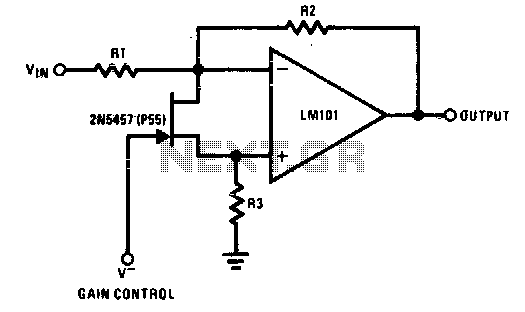
The 2N5457 functions as a voltage-variable resistor with a maximum RdS of 800 ohms. Given that the differential voltage on the LM101 is in the low millivolt range, the 2N5457 JFET exhibits linear resistance over several decades, offering excellent...

This notch filter is beneficial for tunable band-reject applications in the audio range. The specified values will provide a tuning range of approximately 300 to 1500 Hz. The notch filter is designed to attenuate a specific frequency while allowing others...