
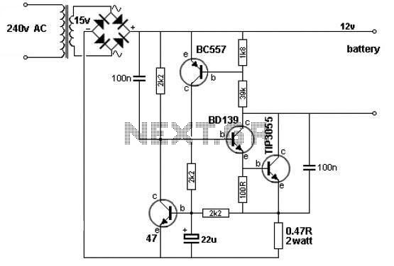
Battery charger circuit Schematic Diagram
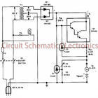
The charger circuit is designed to efficiently charge a battery pack consisting of six cells, each rated at 2.4 volts. The total charging voltage of 14.4 volts is derived from the multiplication of the individual cell voltage by the number of cells in series. The pulsing mechanism operates at a frequency of 120 Hz, which facilitates effective energy transfer to the battery, ensuring optimal charging performance while minimizing heat generation.
The circuit typically includes a power supply unit that converts the AC mains voltage to a suitable DC voltage, which is then regulated to provide a stable output of 14.4 volts. This regulation is crucial to prevent overcharging, which can lead to battery damage or reduced lifespan.
A control circuit, often utilizing a microcontroller or dedicated charging IC, manages the pulse width modulation (PWM) signals sent to the battery. This modulation allows for precise control over the charging current and voltage, adapting to the battery's state of charge. Additionally, safety features such as overcurrent protection, thermal shutdown, and reverse polarity protection may be integrated to enhance reliability and safety during operation.
The output stage of the charger may consist of a switching regulator or a linear regulator, depending on the design requirements, efficiency considerations, and cost constraints. Capacitors and inductors are typically employed in the output stage to filter the voltage and current, smoothing out any ripples that may arise from the pulsing action.
Overall, this battery charger circuit represents a well-engineered solution for charging multi-cell battery packs, adhering to manufacturer specifications while incorporating modern electronic design principles to ensure safety, efficiency, and performance.This cahrger based on chargeing voltage 2, 4 Volts per cell, in accordance with most manufacterers recomendation. This circuit pulses the battery under with 14. 4 Volts ( 6 cells x 2, 4 volts per cell) at a rate 120 Hz. You are reading the Circuits of Battery charger circuit And this circuit permalink url it is 🔗 External reference
Related Circuits
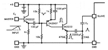
The UC3842, UC3843, UC3844, and UC3845 series of oscillators can generate synchronization pulses without requiring numerous external components. The following circuit illustrates the Sync Pulse Generator Circuit Diagram for the UC3842/3/4/5. This sync pulse circuitry is capable of operating...
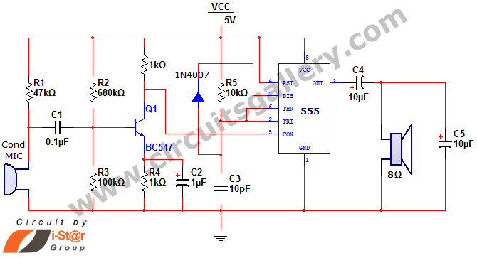
This document discusses a simple project utilizing the 555 timer IC. The 555 timer IC can be configured as an audio amplifier using an astable multivibrator configuration. It performs pulse width modulation (PWM) on an audio signal. The current...
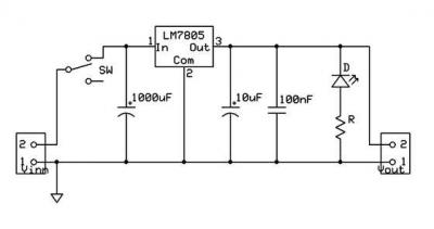
A micro power supply unit (PSU) is designed to power a breadboard with a voltage output of 5 volts. It can be connected to a 9V battery, a 12V source, or any other direct current (DC) power supply ranging...
This simple circuit is based on the well-known integrated circuit LM3915. The main characteristic of this integrated circuit is its ability to manage 10 Light Emitting Diodes (LEDs) in a logarithmic scale, with a 3dB difference between the LEDs,...
A simple 12V battery charger circuit can be designed using a TIP3055 power transistor to limit the current to the battery. The circuit turns off when the battery voltage reaches approximately 14V or if the current exceeds 2A. This...
This circuit is designed to achieve exceptional popularity, as evidenced by its record-breaking views and comments on the referenced website. As of May 3, 2013, it has garnered 760,191 views and 412 comments, with 116 views recorded on that...