
Battery Charger Regulator
The operation of car battery chargers typically involves converting alternating current (AC) from a wall outlet into direct current (DC) suitable for charging lead-acid batteries. Standard chargers often lack sophisticated charging algorithms and may not include features such as automatic shut-off or float charging, which are essential for preventing overcharging.
When a charger remains connected to a battery beyond the recommended charging time, the continuous input of current can lead to excessive voltage levels within the battery. This overcharging can result in several detrimental effects, including the gassing of electrolyte, which diminishes the battery's capacity and lifespan. In severe cases, it may even lead to thermal runaway, where the battery overheats and can potentially cause leakage or explosion.
To mitigate these risks, smart chargers are available that utilize microcontroller-based systems to monitor the battery's state of charge (SoC). These chargers can automatically adjust the charging current and voltage based on the battery's needs, transitioning through different charging phases such as bulk, absorption, and float. This ensures that the battery is charged efficiently and safely without the risk of overcharging.
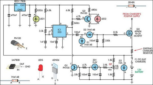
In addition, incorporating temperature sensors into the charging circuit can further enhance safety by allowing the charger to adjust its operation based on the battery temperature, preventing overheating. By using such advanced charging technologies, users can maintain the health and longevity of their car batteries while minimizing the risks associated with prolonged charging.Most off-the-shelf car battery chargers cannot not be left connected to the battery for long periods of time as over-charging and consequent battery damag.. 🔗 External reference
Related Circuits
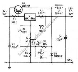
A switching voltage regulator circuit depicted in the schematic diagram can serve as a cost-effective solution for high-efficiency electronic circuit requirements. The switching voltage regulator circuit operates by converting a higher input voltage to a lower output voltage with minimal...
As the circuit operates, the three sets of diodes with their isolation capacitors build up an increasing voltage on capacitor C1. The voltage at point B will also increase and be about twelve volts less than the voltage on...
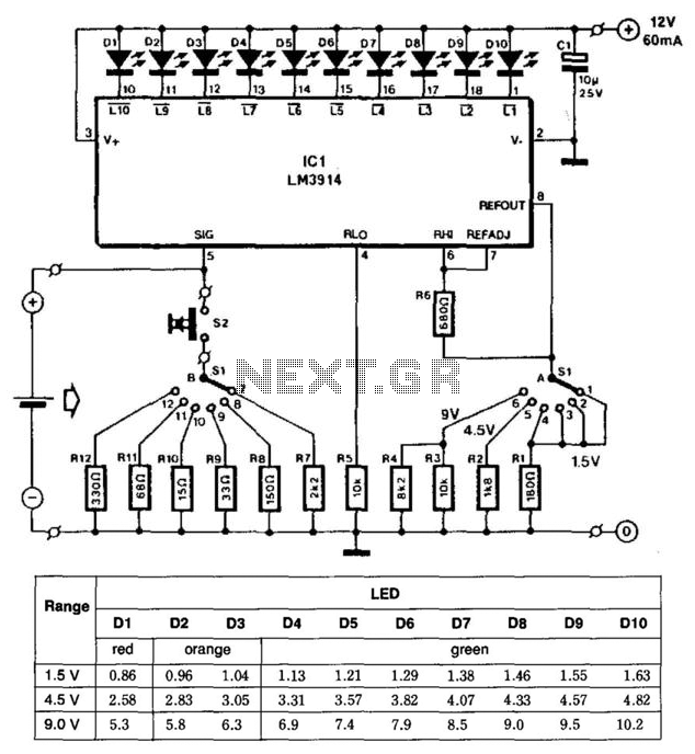
This battery tester utilizes an LM3914 bar-graph driver integrated circuit (IC). Switch SI selects the load on the battery being tested and programs the voltage range. Switch S2 applies the load to the battery under test. A table provides...
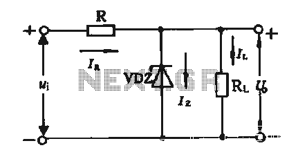
The simple voltage regulator circuit consists of a silicon regulator and a resistor. It is designed to rectify and filter DC voltage, as illustrated in the accompanying figure. The voltage regulator is connected in parallel with the load, and...
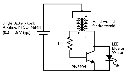
This circuit is commonly referred to as a Joule Thief, and it has been frequently encountered in various electronics videos on YouTube. The Joule Thief is a simple, low-cost circuit designed to extract energy from a single-cell battery, particularly when...
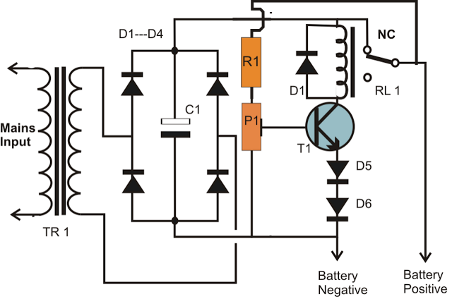
A simple battery charger circuit is described, utilizing a single transistor for voltage detection and automatically disconnecting the battery from the supply when fully charged. The circuit's high voltage trip point is set to switch off the charging voltage...