
simplest smf automotive battery charger
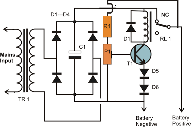
The described battery charger circuit employs a single transistor, specifically the BC547, to manage the charging process of an automotive battery. The circuit is designed to automatically disconnect the battery from the power supply when it reaches a fully charged state, indicated by a voltage of approximately 14 volts. The transistor serves a dual purpose: it detects the voltage level and controls the charging state to prevent overcharging.
The critical aspect of this design is the establishment of two voltage thresholds: the upper threshold, set at 14 volts, and the lower threshold, initially around 10 volts. The lower threshold of 10 volts is problematic, as allowing the battery voltage to drop to this level risks potential damage to the battery. To mitigate this issue, the circuit incorporates two diodes in series with the emitter of the transistor. This configuration effectively modifies the lower threshold by reducing it by 1.4 volts, raising the operational threshold to a safer level of 11.4 volts.
This adjustment ensures that the battery will not be allowed to discharge to dangerously low levels before the charging process resumes. The use of diodes introduces a small voltage drop, which is essential for enhancing the overall functionality and reliability of the charger. The design is both economical and efficient, making it suitable for automotive applications where battery maintenance is crucial.
In summary, the circuit achieves a balance between cost and functionality, providing an intelligent solution for automotive battery charging. The automatic disconnection feature, combined with the improved voltage thresholds, ensures that the battery remains in optimal condition without the risk of over-discharge or overcharging, making this circuit an effective choice for battery management.A very simple battery charger circuit is described in this article, which uses just a single transistor for the voltage detection as well as for automatically disconnecting the battery from the supply when it gets fully charged. This adjustment becomes the high voltage trip point of the circuit and is used to switch OFF the charging voltage to
the battery when it gets fully charged or its voltage reaches around 14 volts. Typically a general purpose transistor like the one which is shown (BC547) when adjusted to switch ON at 14 volts may have the lower threshold of around 10 volts, when it might get just switched OFF. The lower threshold of 10 volts is dangerously low and we cannot wait for the circuit to restart the charging process until the battery voltage falls to this dangerous 10 volts level.
Therefore to eliminate this issue the circuit needed to somehow reduce the hysteresis level. This is done by introducing a couple of diodes at the emitter of the transistor. By inserting the two diodes in series with the emitter of the transistor, we force the transistor to switch off 1. 4 V earlier than its normal specified limit of 10 volts. Therefore now the lower operating threshold of the circuit becomes 10 + 1. 4 = 11. 4 volts, which may be considered just OK for the battery and for the automatic restart of the charging process.
Having both the thresholds updated as per the standard charging requirements, we now have an automatic automotive battery charger that`s not only cheap to build but also smart enough to take care of the battery charge conditions very efficiently. 🔗 External reference
Related Circuits
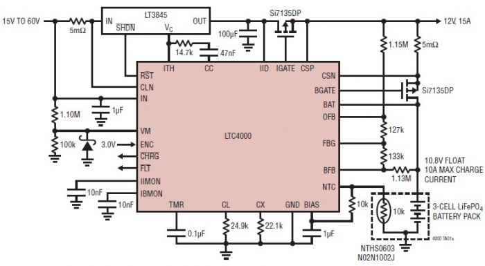
The LTC4000 high voltage controller, developed by Linear Technology, can be utilized to create a straightforward high current LiFePO4 battery charger. This charger delivers a fixed output voltage of 12 volts with a maximum output current of 15 A....
This circuit utilizes the widely available LM3914 integrated circuit (IC), which is straightforward to operate and does not require external voltage regulators due to its built-in voltage regulator. It can be powered from various sources. When the test button...
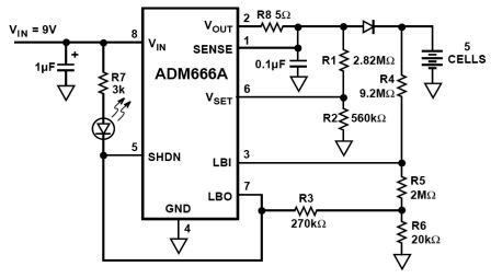
NiMH charger circuit diagram using ADM66A. Related searches include charger circuit, NiMH charger circuit, lead acid battery charger circuit, LiPo charger circuit, automatic battery charger circuit, simple battery charger circuit, lithium battery charger circuit, charger circuit diagram, and 12V...
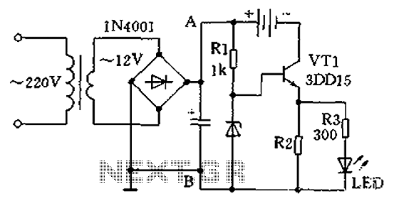
A practical single-tube constant current charger is illustrated, utilizing a transistor (VT1) that plays a crucial role in maintaining a constant current. The current value is determined by the voltage regulator and resistor R2. The general output voltage is...
A Lithium Polymer Ion Battery is included with the Lilypad Development Board from SparkFun. There is an inquiry regarding whether the battery will charge when it is connected to the Lilypad Arduino while simultaneously connecting the Lilypad Arduino using...
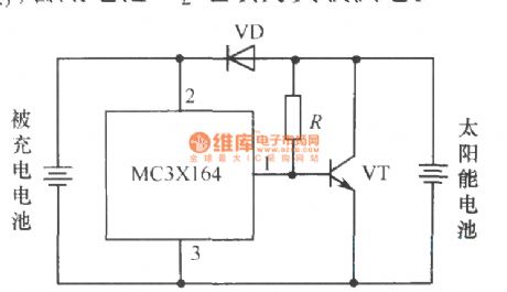
The following circuit illustrates a current-limited solar battery charger circuit diagram. This lead-acid or Ni-Cd battery charger circuit diagram utilizes solar energy to charge a 6-volt, 4.5 Ah rechargeable battery for various applications. It represents a straightforward solar battery...