
Free energy battery charger
The RF antenna connected to a circuit configured to convert the RF signals to Direct Current. The radio frequency signals received by the antenna are transmitted to two leads, one being rectified to produce positive voltage and the other rectified to produce negative voltage. The positive voltage lead is connected directly to a positive output line and the negative voltage lead is connected directly to a negative output line. The positive output line is connected to a pair of bus lines through a first pair of capacitors, while the negative output line is connected to the pair of bus lines by a second pair of capacitors. Placed between the first bus line and the positive output line is a reverse diode of negative polarity, while placed between the negative output line and first bus line is a reverse diode of positive polarity. The positive and negative output lines are connected to one another through an inductor which is in parallel with the capacitors of the first and second pair connected between the second bus line and the positive and negative output lines.
There has long been interest in technology directed to transmitting electrical energy over a distance without using wires. Development of such a technology has enormous potential. This was first recognized by Nikola Tesla who in 1899 constructed a 200-foot Tesla coil rated at 300 kilowatts at 150 kilocycles. Tesla hoped to set up standing waves of electrical energy around the whole surface of the earth, so that receiving antennas set at optimum points could tap the power when needed. Tesla was able to light hundreds of lamps at a distance of about 40 kilometers with his device without using wires. The scheme has generally remained a scientific curiosity but has provided the initial groundwork for current developments wherein attempts are being made to transmit power using microwaves. However, power transmitted by microwaves is envisioned in the form of a beam of very high intensity which is focused from a microwave generator to a receiving antenna. This technology is envisioned as being used for many types of purposes; however, the focused microwave beam is not suitable for many applications because the beam must be directed toward a receiving antenna and cannot be transmitted through most objects, including living objects, without destroying those objects.
This invention relies on converting energy from standing waves which are emitted from radio frequency antennas in the RF range rather than the microwave range. Of particular interest are very low frequencies which are not used in communications and are available for transmitting power. Also of interest are the low frequency waves emitted by the earth due to pulsing of its magnetic field. These low frequency standing "earth" waves can be picked up by receivers tuned to them.
The circuit design employs three sets of diodes, which serve to rectify and isolate the voltage generated by the RF antenna. The isolation capacitors play a critical role in charging capacitor C1, which is pivotal in controlling the thyristor operation. The thyristor, specifically the BT151-800R model, is capable of handling high voltages and currents, making it suitable for applications involving significant power pulses. The interaction between the neon tube and the thyristor is crucial for the timing and switching of the circuit, allowing for repeated cycles of charging and discharging.
The RF antenna's configuration is significant for optimizing power collection. The recommendation for aerial placement between structures promotes maximum signal capture, while the use of adequately sized insulated wire is essential to prevent energy loss and ensure efficient operation. The inclusion of capacitors and diodes in the output stage is designed to stabilize the output voltage and ensure safe operation of connected loads. The inductor's role in the circuit further enhances the efficiency of energy transfer between the positive and negative output lines.
Overall, this circuit exemplifies innovative methods for harnessing ambient energy through RF signals, with potential applications in wireless power transmission systems. The historical context provided by Tesla's work underscores the ongoing relevance and potential of such technologies in modern energy solutions.As the circuit operates, the three sets of diodes with their isolation capacitors, build up an increasing voltage on capacitor ?C1?. The voltage at point ?B? will also increase and be about twelve volts less than the voltage on capacitor ?C1?. Eventually, that voltage will rise high enough to cause a discharge through the tiny neon tube and that current pulse flows through the Gate connection ?G?
of the thyristor, switching it on. Once switched on, the thyristor stays on until capacitor ?C1? has been discharged, after which, the thyristor switches off and the process starts all over again. The amount of power in these pulses is considerable and the thyristor gets quite warm when the circuit is running. The BT151-800R thyristor can handle as much as 800 volts and pass 7.5 amps of current continuously. An important point to note is that the power available from this circuit increases with additional aerials. With two aerials connected, the power is doubled and with three aerials the power is tripled. That is, each additional aerial provides as much power as the first aerial did and there does not appear to be any limit to the number of aerials which can be connected.
The suggestion is that the aerial is suspended between the eaves of a house and a nearby tree, but I don?t know anybody who would be able to do that. The longer the aerial or the greater the number of aerials connected, the greater the charging power available.
The aerial wire should be not less than 0.5 mm in diameter and it needs to be insulated from it?s supports ? plastic cord can be used for that. The RF antenna connected to a circuit configured to convert the RF signals to Direct Current. The radio frequency signals received by the antenna are transmitted to two leads, one being rectified to produce positive voltage and the other rectified to produce negative voltage.
The positive voltage lead is connected directly to a positive output line and the negative voltage lead is connected directly to a negative output line. The positive output line is connected to a pair of bus lines through a first pair of capacitors, while the negative output line is connected to the pair of bus lines by a second pair of capacitors.
Placed between the first bus line and the positive output line is a reverse diode of negative polarity, while placed between the negative output line and first bus line is a reverse diode of positive polarity. The positive and negative output lines are connected to one another through an inductor which is in parallel with the capacitors of the first and second pair connected between the second bus line and the positive and negative output lines.
There has long been interest in technology directed to transmitting electrical energy over a distance without using wires. Development of such a technology has enormous potential. This was first recognized by Nikola Tesla who in 1899 constructed a 200 foot Tesla coil rated at 300 kilowatts at 150 kilocycles.
Tesla hoped to set up standing waves of electrical energy around the whole surface of the earth, so that receiving antennas set at optimum points could tap the power when needed. Tesla was able to light hundreds of lamps at a distance of about 40 kilometers with his device without using wires.
The scheme has generally remained a scientific curiosity but has provided the initial groundwork for current developments wherein attempts are being made to transmit power using microwaves. However, power transmitted by microwaves is envisioned in the form of a beam of very high intensity which is focused from a microwave generator to a receiving antenna.
This technology is envisioned as being used for many types of purposes, however, the focused microwave beam is not suitable for many applications because the beam must be directed toward a receiving antenna and cannot be transmitted through most objects, including living objects, without destroying those objects. This invention relies on converting energy from standing waves which are emitted from radio frequency antennas in the RF range rather than the microwave range.
Of particular interest are very low frequencies which are not used in communications and are available for transmitting power. Also of interest are the low frequency waves emitted by the earth due to pulsing of its magnetic field.
These low frequency standing "earth" waves can be picked up by receivers tuned to them. 🔗 External reference
Related Circuits
Photo. This is the test circuit -the basic driver is only two transistors, two resistors, the circuit was evaluated using a white LED, but when it was time to button it up and archive it, I replaced the expensive...
Convert the smart cards into manual push buttons to control energy consumption, alleviating the consumer's concern about sourcing smart cards, especially given the limited supply in the area. The proposed modification involves replacing the current smart card system with...
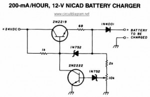
This NiCAD battery charger circuit charges the battery at 75 mA until it is fully charged, after which it reduces the current to a trickle rate. It can completely recharge a dead or unpowered battery in 4 hours, and...
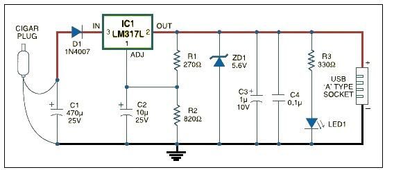
USB car charger adapter circuit design using LM317 regulator circuit The USB car charger adapter circuit utilizing the LM317 voltage regulator is designed to convert a car's 12V DC power supply into a stable 5V output, suitable for charging USB-powered...
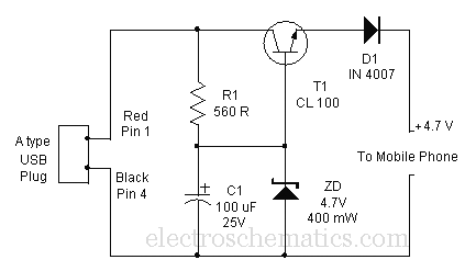
Comprehensive information about a USB cellphone charger circuit is available for learning and downloading online. The USB cellphone charger circuit is designed to convert AC mains voltage into a stable DC voltage suitable for charging mobile devices. This circuit typically...
This very simple circuit uses a transformer, two diodes, a capacitor, and an ammeter. To charge a battery, just connect the + and - terminals of the circuit to the corresponding terminals of the battery. When the battery is...