
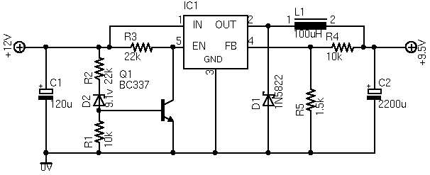
Battery charger using LM350
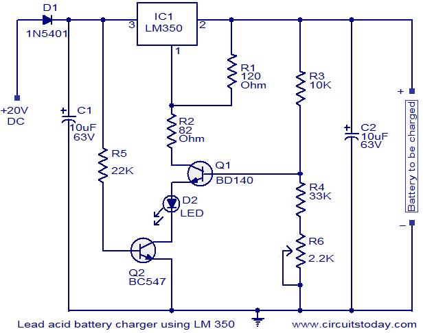
The circuit is designed to efficiently charge 12V lead-acid batteries, making it suitable for applications where reliable battery maintenance is crucial. The LM350 voltage regulator is central to this design, providing a stable output voltage that can be fine-tuned to meet specific charging requirements. The use of a potentiometer (R6) allows users to adjust the output voltage within the range of 13V to 15V, accommodating variations in battery specifications or charging conditions.
Transistor Q1 (BD140) serves a dual purpose in the circuit: it acts as a temperature sensor and regulates the charging process based on ambient temperature changes. The negative temperature coefficient characteristic of Q1 ensures that as the temperature increases, the output voltage decreases, which helps to prevent overheating of the battery during charging. This feature is essential for maintaining battery health and longevity.
Transistor Q2 plays a critical role in preventing backflow current from the battery to the charger when mains power is not present. This is particularly important in battery management systems, where uncontrolled discharging could lead to battery damage or reduced performance.
The circuit's design incorporates resistors R3 and R4, which work in conjunction with R6 to set the base current of Q1, thereby influencing the response of the circuit to temperature changes. The calculated temperature coefficient of approximately -8mV/°C ensures that the charging voltage is adjusted appropriately, providing a safe and effective charging environment for the battery.
The LED indicator serves as a simple yet effective visual cue, alerting users to the presence of mains power. This feature enhances the usability of the circuit, ensuring that users can quickly ascertain the operational status of the charging system.
In summary, this circuit represents a robust solution for charging 12V lead-acid batteries, combining the functionality of a voltage regulator with temperature compensation and user-friendly features. Its design emphasizes safety, efficiency, and adaptability, making it suitable for various charging applications.Here is a simple circuit using IC LM 350, which can be used for charging 12V lead acid batteries. This circuit is perfect for constant charging 12V lead acid batteries. The circuit is designed as a constant voltage source with a negative temperature coefficient. The transistor Q1 (BD 140) is used as the temperature sensor. The transistor Q2 is used to prevent the battery from discharging through R1 when the mains power is not available. The circuit is designed based on the voltage regulator IC LM350. The output voltage of the charger can be adjusted between 13-15 V by varying the POT R6. The LM350 will try to keep the voltage drop between its input pin and the output pin at a constant value of 1. 25V. So there will be a constant current flow through the resistor R1. Q1 act here as a temperature sensor with the help of components R6/R3/R4 which more or less control the base current of Q1.
As the emitter/base connection of transitorQ1, just like any other semiconductor, contains a temperature coefficient of -2mV/ °C, the output voltage will also show a negative temperature coefficient. That one is only a factor of 4 larger, because of the variation of the emitter/basis of Q1 multiplied by the division factor of P1/R3/R4.
This results in approximately -8mV/ °C. The LED will glow whenever the mains power is available. 🔗 External reference
Related Circuits
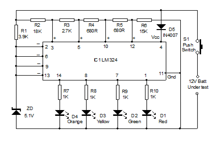
Battery Volt Meter Circuit Diagram. This circuit is designed to monitor the voltage level in Lead Acid or Tubular batteries. It provides four LED indicators to represent the voltage levels ranging from 9 volts to 14 volts. The battery voltmeter...
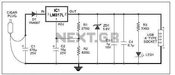
This USB car charger circuit adapter is designed for use with a car's cigarette lighter socket. It functions as a DC-DC power converter, effectively converting the 12V voltage from the car battery into a stable 5V output. This circuit...
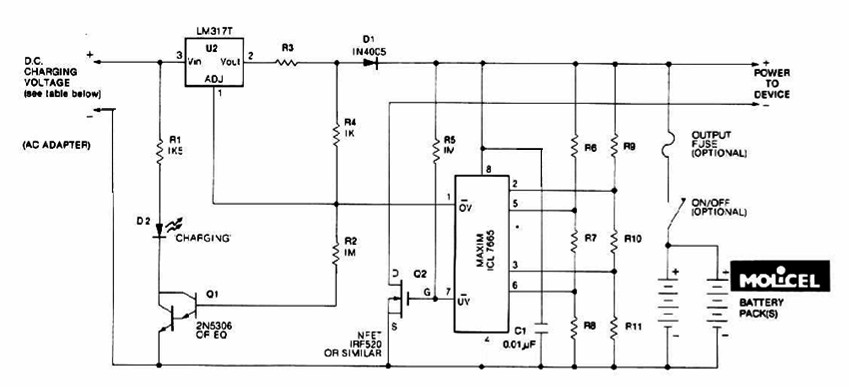
The charging system described is designed for multi-cell lithium battery packs comprising two to six series-connected cells or series/parallel configurations. The schematic diagram originates from the lithium battery charger power supply circuit. This circuit is specifically intended for charging...
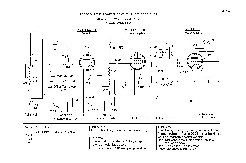
The basic regenerative design is quite common. Before the schematic is created, there is a "concept stage," followed by the "available components stage," returning to the "concept stage," then moving on to the "mechanical/electrical layout stage," and finally sketching...
The ASUS Eee is an exceptional ultra-portable notebook that includes nearly all the necessary features for technology enthusiasts while omitting unnecessary elements. Additionally, it boasts an impressive build quality. The ASUS Eee series is designed with portability and functionality in...
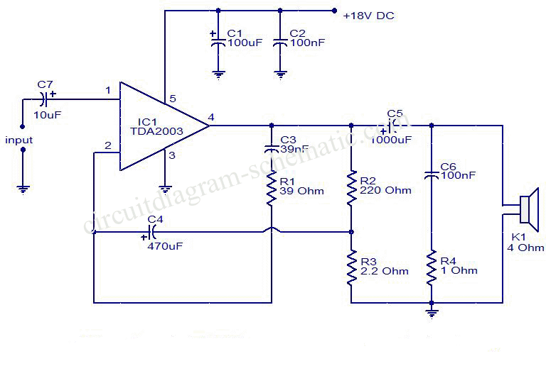
This is a circuit diagram of an audio amplifier circuit featuring a 10W power amplifier using the TDA2003 integrated circuit from SGS Thomson. The IC is capable of delivering 10W into a 4-ohm load at a supply voltage of...