
Battery Volt Meter

The battery voltmeter circuit utilizes a series of resistors and a voltage divider to scale down the battery voltage to a range suitable for the LED indicators. The circuit is typically powered by the battery itself, ensuring that it is always operational as long as the battery is functional.
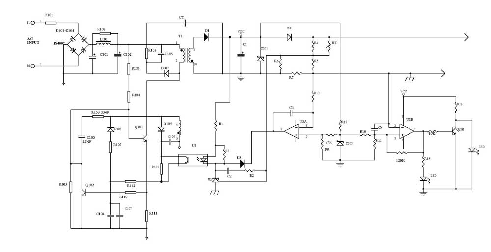
The four LEDs are configured to illuminate at specific voltage thresholds:
- The first LED lights up when the voltage is below 9 volts, indicating a low battery condition.
- The second LED activates between 9 volts and 10.5 volts, signaling a warning that the battery is in a low state of charge.
- The third LED turns on for voltages between 10.5 volts and 12.5 volts, indicating a moderate charge level.
- The fourth LED lights up when the voltage is between 12.5 volts and 14 volts, signifying a fully charged battery state.
The circuit may include a potentiometer for calibration, allowing for precise adjustment of voltage thresholds according to the specific characteristics of the battery being monitored. Additionally, a transistor can be employed to drive the LEDs, ensuring that they can handle the current without damaging the components.
This battery voltmeter circuit is a practical solution for users who need to regularly monitor their battery voltage, providing a visual indication of the battery's health and charge status, thus aiding in maintenance and preventing potential battery failures.Battery Volt Meter Circuit Diagram. Here is an ideal circuit to monitor the voltage level in Lead Acid or Tubular battery. It gives four LED indications to give the voltage level between 9 volts and 14 volts 🔗 External reference
Related Circuits
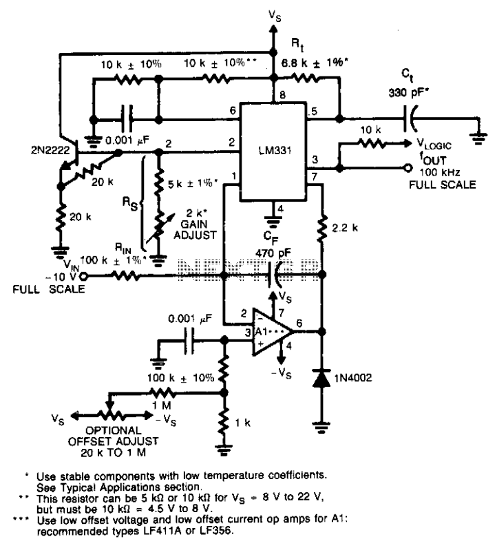
This circuit utilizes a conventional operational amplifier in conjunction with a feedback capacitor (CF) to perform integration. When the output of the integrator exceeds the nominal threshold level at pin 6 of the LM131, it triggers the timing cycle....
The DS2715 is a comprehensive NiMH (Nickel Metal Hydride) smart charger solution featuring load detection, making it ideal for cost-effective applications. The DS2715 smart charger integrates several key functionalities designed to enhance the charging process for NiMH batteries. It employs...
The following circuit illustrates a High Voltage, Low Current Supply. Features: This circuit is utilized for applications such as biasing gas-discharge tubes, radiation detectors, and similar devices. The High Voltage, Low Current Supply circuit is designed to provide a stable...

The DC output of the voltage multiplier ranges from 1,000 volts to 30,000 volts, with the actual voltage depending on the size of the cathode ray tube (CRT) and its application. Voltage multipliers can also serve as primary power...
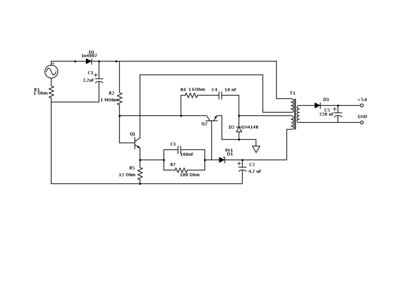
An old Nokia phone charger with a 5.6 V output was modified to provide 12 V by changing the Zener diode from a 9.1 V to a 16 V component. The circuit is mostly understood, but clarification is needed...
Several schematic drawings of battery charger circuits are provided. These circuits cover 5W to 200W for NiCd, NiMH, Lead-Acid, Li-Ion/Polymer, and LiFePO4 battery packs. The charger circuit files aim to assist users in selecting the appropriate chargers and to...