
Battery over-discharge protection circuit diagram
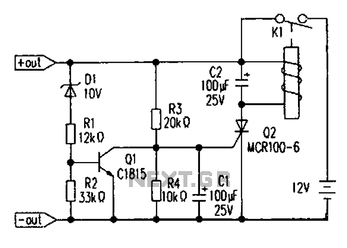
For component selection, the trip switch can be a color TV power switch with a relay, model KDC-A04-8Y, which has a dual switching current of 5A, allowing for a maximum operating current of 10A when paralleled. The electromagnetic coil has a DC resistance of about 25 ohms and requires a measured coil voltage of 7V to activate. Q1 can be selected as MCR100-6, which has an extremely sensitive gate trigger current (10 µA to 30 µA) and an on-state voltage drop of approximately 0.8V. The regulator diode D1 is chosen to operate at a protection circuit voltage of -0.7V, and in the circuit, R1 experiences a partial pressure drop below 0.2V, which can be disregarded.
This circuit detects a current of 1.1 mA, primarily through R1 with a branch current of 0.35 mA to 0.1 mA, and through R2 with a branch current of 0.5 mA to 0.75 mA, depending on the selected operating current of the trip switch K1 coil's DC resistance. The KDC-A04-8Y relay has an operating current of about 400 mA, with an operating time of less than 0.2 seconds.
Additionally, two other micro-power battery over-discharge protection circuits are illustrated in the accompanying diagrams. The voltage detection in these circuits is performed using a TL431 precision voltage regulator, which controls the turn-off voltage point through precision adjustment via VR1. The TL431 is selected for its high control accuracy, typically 50 ppm/temperature coefficient, small current consumption, and other advantages. In this circuit, the TL431 cathode voltage range is 1.9V to 2.7V, with a requirement of approximately 2.7V to trigger Q2. The diagrams above and below illustrate two connection configurations. The first configuration uses resistors R5 and R4, while the second configuration employs the forward voltage drop of an ordinary red light-emitting diode (approximately 1.7V) for division. It is noted that the control electrode of the cathode voltage can trigger conduction at 0.65V to 0.7V. The use of standard red light-emitting diodes is specified for the circuit. Battery discharge will cause plate acidification, affecting the normal life of the battery. To solve this problem, we designed a special micro-power battery over-discharge prot ection circuit, as shown above, the circuit has a very low detection current (detected current l.lmA), after the protection circuit will no longer consume energy, anti-interference ability and so on. A schematic of the circuit After manual closing trip switch Kl, energized circuit into operation. First, because the voltage across C1 can not be mutated, keeping close to 0V, 02 deadline, when the battery voltage 10.7V, the regulator D1 conducts, al saturated conduction, Q2 gate voltage cut-off due to lack of triggers, K1 does not operate, batteries and post-stage circuit in a closed working condition, when the battery voltage 10.7V, the regulator diode D1 is off, Ql is turned oFF, the resistor R3 to charge the capacitor C1.
When the voltage across C1 reaches approximately 0.6V, Q2 is triggered thyristor conduction, tripping switching operation, after disconnecting the load circuit level. Second, component selection Trip switch can choose color TV power switch with relay, model KDC-A04-8Y, switching current dual 5A, can be paralleled becomes maximum operating current of 10A, which included an electromagnetic coil DC resistance of about 25, the measured coil voltage 7V can pull.
Ql selection MCR100-6, MCR100-6 have extremely sensitive gate trigger current (trigger current of 10 A ~ 30 A), on-state voltage drop characteristics (pressure drop in the circuit is measured 0.8V). When the regulator is selected Dl protection circuit voltage minus 0.7V, as no suitable regulator can be used in tandem with both the regulator (the circuit operation, Rl partial pressure below 0.2V, it can drop can be ignored).
III Remarks This circuit detects the current 1.1mA, mainly through R1 branch current 0.35mA ~ 0.1mA, by R2 in the branch current 0.5mA ~ 0.75mA, depending on the selected operating current trip switch K1 coil DC resistance. The test KDC-A04-8Y operating current of about 400mA, operating time is less than 0.2 seconds. Fourth, the other two micro-power battery over-discharge protection circuit See the circuit diagrams above and below its former level voltage detection is accomplished TL431 precision voltage regulator that controls the turn-off voltage point via precision adjustment VR1.
TL431 is chosen due to its high control accuracy, typically 50ppm/temperature coefficient equivalent full range of small current consumption and many other advantages in this circuit. Because this circuit TL431 cathode voltage range of 1.9V ~ 2.7V, to meet the TL431 cathode voltage is about 2.7V trigger Q2, which provides the diagrams above and below two connections.
The figure is dividing by R5 (and later stage R4), the following figure is used LEDs forward voltage drop (ordinary red light-emitting diode micro-current of about 1.7V forward voltage drop) for dividing (02 Found the control electrode of the cathode voltage 0.65V ~ 0.7V can trigger conduction). NOTE: LED use an ordinary red light-emitting diodes.
Related Circuits
This simple-to-construct water fishing thermometer circuit is intended for use in sports applications, such as fishing contests. A sensor measures... This water fishing thermometer circuit is designed to provide accurate temperature readings of water, making it an essential tool for...

A high-input-resistance operational amplifier (op-amp), a bridge rectifier, a microammeter, and several discrete components are necessary to implement this versatile circuit. This circuit can measure DC, AC RMS, AC peak, or AC peak-to-peak voltage by simply altering the resistor...
This circuitry provides a magnification of 1,200,000 times, with a bandwidth ranging from 0.5 to 14 MHz. The input impedance is 700 ohms, while the output impedance is 35 ohms when measured at 5 MHz. The output noise level...
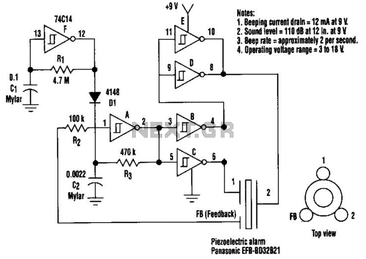
This circuit generates a loud sound of 110 dB using a 9 V power supply. It incorporates a single 74C14 (CD40106B) CMOS hex inverting Schmitt-trigger IC, which is utilized with a piezoelectric device that includes a feedback terminal. The...
This is a simple game circuit designed for multiplayer enjoyment. The objective is to score one hundred points within a limited timeframe. To restart the game, the S1 button switch must be pressed. It is important to ensure that...

The 10A H-Bridge Motor Controller circuit appears straightforward, but several critical aspects should not be overlooked. The primary components utilized in the circuit include the TIP147, TIP142, and 2N2222 transistors. The power supply circuit operates at +12V, which is...
Warning: include(partials/cookie-banner.php): Failed to open stream: Permission denied in /var/www/html/nextgr/view-circuit.php on line 713
Warning: include(): Failed opening 'partials/cookie-banner.php' for inclusion (include_path='.:/usr/share/php') in /var/www/html/nextgr/view-circuit.php on line 713