
high resistance voltmeter circuit diagram

The circuit utilizes a high-input-resistance op-amp to ensure minimal loading on the voltage source being measured, which is critical for accurate measurements. The bridge rectifier converts AC voltages to a DC equivalent, allowing for the measurement of varying AC signals. The microammeter serves as the display element, providing a visual representation of the measured voltage.
To measure different voltage types, the resistor connected between the inverting input terminal and ground can be adjusted. For DC measurements, a specific resistor value is used, while for AC RMS, AC peak, and AC peak-to-peak measurements, different resistors will be selected based on the desired measurement type. The configuration of the op-amp in this circuit is typically in a non-inverting configuration, where the input voltage is applied to the non-inverting terminal, ensuring that the output voltage is in phase with the input signal.
The bridge rectifier is composed of four diodes arranged in a configuration that allows for the conversion of both halves of the AC waveform into a usable DC voltage. This output is then fed into the microammeter, which is calibrated to display the corresponding voltage levels based on the input signal characteristics.
In summary, this circuit is highly adaptable, enabling the user to measure a variety of voltage types with a simple adjustment of resistor values, making it a valuable tool in electronic measurement applications.A high-input-resistance op-amp, a bridge rectifier, a microammeter, and a few other discrete components are all that are required to realise this versatile circuit. This circuit can be used for measurement of dc, ac rms, ac peak, or ac peak-to-peak voltage by simply changing the value of the resistor connected between the inverting input terminal
of the op-amp and ground. The voltage to be measured is connected to non-inverting input of the op-amp. 🔗 External reference
Related Circuits
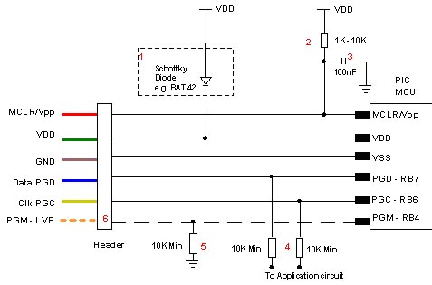
Microchip does not recommend any specific circuit for In-Circuit Serial Programming (ICSP). Various diagrams exist for different tools, such as Pro Mate and PICKit2, which feature similar circuitry with minor variations. Some schematics may suggest resistor values that are...
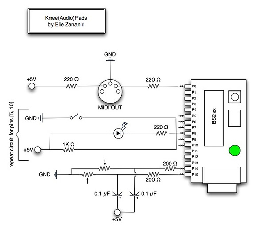
A few nice MIDI controller interfaces were discovered. The Knee(Audio)Pads are a wearable MIDI device. The MIDI controller interfaces mentioned provide innovative solutions for music production and performance. The Knee(Audio)Pads, in particular, represent a unique advancement in wearable MIDI technology....

This document provides technical details regarding the hardware and software of a complete imaging system that utilizes a fast CCD sensor and a 41 Msample/s A/D converter. This system is capable of acquiring full-frame digitized images at a resolution...

A basic circuit to trigger a silicon-controlled rectifier (SCR) is illustrated in Figure 67-1A. This circuit has the limitation that the blocking voltage of the photonic coupler output device dictates the circuit's blocking voltage, despite the SCR's higher voltage...

The motors will be powered by the full source voltage, so it is important to ensure that this does not cause the robot to operate too quickly. The Firebot utilizes GM3 motors powered by a 9V battery; however, in...

The application circuit operates the device as illustrated below, allowing for intermittent lighting in specific situations (e.g., during surgery). It utilizes an LCE module for blackout emergency lighting, which activates automatically after a power failure, ensuring uninterrupted illumination. In...