
Solid laser range finder receive circuit diagram
This circuit is designed to achieve high levels of magnification while maintaining a broad frequency response, making it suitable for applications requiring precise signal amplification. The input impedance of 700 ohms allows for effective interfacing with various signal sources, ensuring minimal signal loss during the amplification process. The output impedance of 35 ohms at 5 MHz is optimized for compatibility with standard measurement equipment, facilitating accurate signal analysis.
The use of transistors T1 and T2 as direct coupling amplifiers is crucial for maintaining signal integrity across the amplification stages. Direct coupling minimizes phase shifts and frequency response variations that can occur with capacitive coupling. The implementation of negative current feedback in parallel configuration enhances the linearity and stability of the amplification process, reducing distortion and improving overall performance.
The circuit's bandwidth of 0.5 to 14 MHz indicates its versatility in handling a wide range of signal frequencies, making it applicable in various electronic measurement and testing scenarios. The noise level output of 0.6 to 0.8 V is indicative of the circuit's design efficiency, ensuring that the amplified signal remains distinguishable above the noise floor.
In summary, this circuit represents a sophisticated approach to high-gain signal amplification, characterized by its high magnification factor, broad bandwidth, and carefully designed impedance matching, making it suitable for advanced electronic applications.This circuitry zooms in magnification of 1200000 times, the bandwidth is 0.5~14 Mhzs, the input impedance is 700 ?, the output impedance is 35 ?(to measure in the 5 MHZ), the output level of noise is 0.6~0.8 V. In the chart, T1 and T2 are direct coupling amplifiers, and be current negative feedback in parallel connection.
The promotion of T2`s emitter l.. 🔗 External reference
Related Circuits
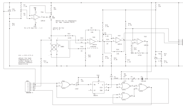
The circuit is powered by the receiver's pack, the current drain is low, especially if compared to drain of servos. U1a VZ2 and Q1 are the current source of the sensor. VZ2 is temperature compensated; use the listed component...
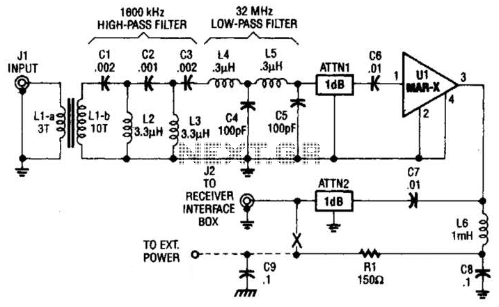
This high-frequency shortwave receiver preamplifier consists of a broadband toroidal transformer (LI-a and Ll-b), a complex LC network that includes a 1600 kHz high-pass filter and a 32 MHz low-pass filter, inductors L2 and L3 (26 turns of #26...
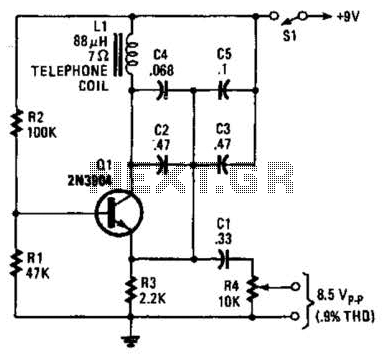
An 88 mH surplus telephone toroidal coil is utilized in a 1 kHz oscillator. It can provide up to 8 V peak-to-peak into a high-impedance load. The total harmonic distortion (THD) is 0.9%. The circuit employs an 88 mH toroidal...
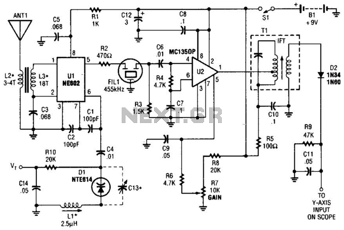
This circuit is designed for monitoring an amateur band or a specific segment of the radio spectrum. It utilizes an NE602 mixer-oscillator chip to generate a 455-kHz intermediate frequency (IF) signal. This signal is amplified by U2 and subsequently...
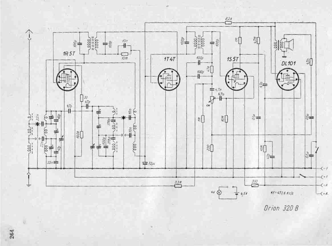
Create a repository of circuits and service data for vintage valve and transistor radios. While many resources are available online, they often come at a cost. The intention is to share circuits and manuals with others rather than profit...
This low-cost project enables audio reproduction from a television without disturbing others. It eliminates the need for wired connections between the TV and loudspeakers. Instead, it utilizes invisible infrared light to transmit audio signals from the TV to the...
Warning: include(partials/cookie-banner.php): Failed to open stream: Permission denied in /var/www/html/nextgr/view-circuit.php on line 713
Warning: include(): Failed opening 'partials/cookie-banner.php' for inclusion (include_path='.:/usr/share/php') in /var/www/html/nextgr/view-circuit.php on line 713