
10A H-Bridge Motor Controller Circuit

The 10A H-Bridge Motor Controller circuit is designed to facilitate the control of a DC motor with a maximum current rating of 10A. The H-bridge configuration allows for bidirectional control of the motor, enabling it to rotate in both clockwise and counterclockwise directions based on the input signals provided. The TIP147 and TIP142 transistors serve as the primary switching elements within the H-bridge, effectively controlling the flow of current to the motor. The 2N2222 transistor is utilized for signal amplification, ensuring that the control signals can adequately drive the larger power transistors.
The power supply section is critical in ensuring that the circuit operates reliably. The use of 100µF capacitors enhances the stability of the power supply by filtering out voltage fluctuations, which is particularly important in motor control applications where inductive loads can cause significant electrical noise. The careful arrangement of the power connections to the collectors and emitters of the transistors is designed to minimize voltage drops and enhance efficiency.
The outputs of the H-bridge are strategically positioned to connect with the motor through the dual terminal block, allowing for easy integration into various applications. The triple terminal block serves a dual purpose: it provides a ground reference and allows for the integration of control signals from a microcontroller or other digital circuitry. The use of thick traces for power connections is essential for handling the high current, reducing resistive losses and preventing overheating.
Signal integrity is maintained through the use of thinner traces for digital connections, which are less susceptible to interference. The design considerations also include the potential need for heatsinks on the power transistors to dissipate heat generated during operation, ensuring long-term reliability and performance of the motor controller.
In summary, this H-Bridge Motor Controller circuit is a robust solution for controlling DC motors, with careful attention to component selection, power management, and signal integrity to ensure optimal performance in various applications.The 10A H-Bridge Motor Controller circuit looks simple but there are some key points that you don`t want to miss. The main devices used in the circuit are the TIP147, TIP142 and 2n2222. The power circuit is the +12v coming in from the terminal block X1-1/X1-2. It connects to a few 100uF capacitors and you might need more or less to help the mot or run smoothly. The power also connects to the very top of the H-bridge (power to collector) and the very bottom (emitter to ground). Outputs 1 and 2 are found in the middle of the H-bridge circuit, these connections feed into one of the dual terminal blocks, which connects to the DC motor.
It is at these points of Output 1/2 where power will flow to drive the motor. The triple terminal block X3-1/X3-2/X3-3 offer a way to connect up some digital circuitry and a ground to control the h-bridge. Input 1 controls one side of the H-bridge and Input 2 controls the other side. Typically when you have high very high currents going through a PCB you want two things: thick traces and proper heatsinks.
You can see the thick traces on the board above going into the dual termianl block connecting to the DC motor. The thin traces are all digital connections. One yellow line still exists, and that is because it was a trace that would cut off a good ground connection to one of the power transistors.
To fix this, a simple jumper wire will be used instead of a PCB trace. The bottom layer (in blue) is used purely for routing the signals to the proper devices. The top layer is used purely for the name of the board and for the top of the through-hole parts. 🔗 External reference
Related Circuits
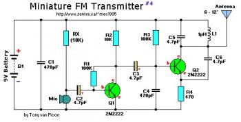
This small FM band transmitter utilizes only two 2N2222 transistors and is capable of transmitting signals up to 1 kilometer away, provided there are no obstacles between the two antennas. The circuit features a microphone preamplifier stage with the...
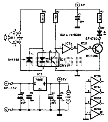
Used for digital control of musical instruments, this transmitter converts digital data signals into equivalent optical signals for a fiber optic cable interface. Optocoupler IC1 provides isolation, driving IC2-a and -b, and T1, ultimately providing a cable driver LED...
After conducting experiments with a rotary encoder connected directly to keyboard switches, it was found that the keyboard controller IC (an Intel P8049AH in this case) is unable to detect pulses that are too narrow. Testing involved rotating the...
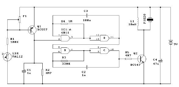
This light alarm schematic circuit is designed using common electronic components, as illustrated in the circuit diagram below. The light alarm circuit will activate an alarm as soon as the drawer is opened and light falls on the Darlington...
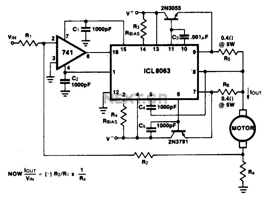
This minimum device circuit can be used to drive DC motors where there is some likelihood of stalling or lock-up. If the motor locks, the current drive remains constant, and the system does not destroy itself. This circuit is designed...
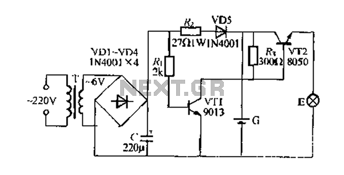
Figure 282 illustrates a simple emergency lamp circuit designed to activate during a power outage. The circuit utilizes a transformer (T) for voltage stepping, diodes (VD1 to VD4) for rectification, and a capacitor (C) for smoothing the output. During...
Warning: include(partials/cookie-banner.php): Failed to open stream: Permission denied in /var/www/html/nextgr/view-circuit.php on line 713
Warning: include(): Failed opening 'partials/cookie-banner.php' for inclusion (include_path='.:/usr/share/php') in /var/www/html/nextgr/view-circuit.php on line 713