
Battery charger circuit using L200

The battery charger circuit described is a straightforward design aimed at efficiently charging a 12V lead-acid battery while providing visual feedback regarding the connection status of the battery. The L200 voltage regulator is the central component, functioning to deliver a stable output voltage suitable for charging. This integrated circuit is capable of handling input voltages higher than the output voltage, making it versatile for various power supply configurations.
The inclusion of a bridge rectifier or a center-tapped rectifier as the power source allows for flexibility in the circuit's application. The rectifier converts AC voltage to DC voltage, which is necessary for the operation of the L200. The output of the rectifier is connected to the input of the L200, ensuring that the voltage supplied to the battery remains consistent.
The charging current is controlled through the resistors R2 and R3, which are connected in parallel. The values of these resistors determine the maximum charging current that can flow to the battery. Additionally, the potentiometer P1 provides an adjustable means to fine-tune the charging current based on the specific requirements of the battery being charged. This feature is particularly useful for accommodating different battery conditions or types.
To enhance the safety and usability of the circuit, a reverse polarity indicator is integrated using a transistor (T1), a diode (D3), and an LED (D5). This configuration ensures that if the battery is connected incorrectly, the red LED will illuminate, alerting the user to the error. This prevents potential damage to the battery and the charging circuit itself.
Furthermore, during the normal charging process, the green LED (D4) serves as a charging indicator, providing visual confirmation that the battery is being charged correctly. This dual LED setup not only improves user experience but also enhances safety by clearly indicating the operational status of the charger.
Overall, this battery charger circuit is designed for simplicity and effectiveness, making it suitable for hobbyist applications and small-scale battery charging needs. Proper component selection and circuit design ensure reliable performance while maintaining user safety through visual indicators.A very simple battery charger circuit having reverse polarity indication is shown here. The circuit is based on IC L200. L200 is a five pin variable voltage voltage regulator IC. The charging circuit can be fed by the DC voltage from a bridge rectifier or center tapped rectifier. Here the IC L200 keeps the charging voltage constant. The charging curr ent is controlled by the parallel combination of the resistors R2 & R3. The POT P1 can be used to adjust the charging current. This circuit is designed to charge a 12 V lead acid battery. The transistor t1, diode D3 and LED are used to make a battery reverse indicator. In case the battery is connected in reverse polarity, the reverse polarity indicator red LED D5 glows. When the charging process is going on the battery charging indicator green LED D4 glows. We aim to transmit more information by carrying articles. Please send us an E-mail to wanghuali@hqew. net within 15 days if we are involved in the problems of article content, copyright or other problems.
We will delete it soon. 🔗 External reference
Related Circuits
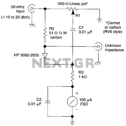
The bridge shown was used for measurements on 50-MHz amateur radio antennas. Rl is a miniature 500 linear potentiometer. The unknown impedance is compared to R2, a 51-ohm resistor. An external signal source is required. The described bridge circuit is...
The 7208 seven-stage decimal counter can be utilized as a frequency counter. It features latch and multiplexing functions, along with direct digital driving circuitry and display driving circuitry. The output frequency of the 7207 IC 6.5536 MHz crystal oscillator...
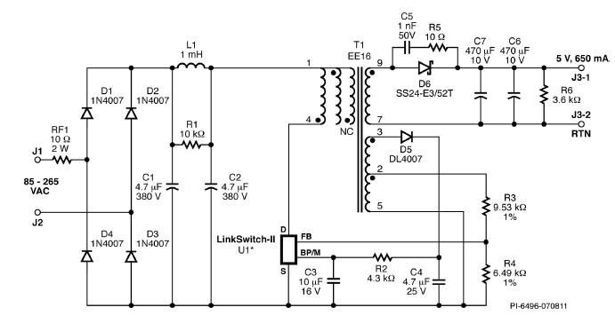
A simple 3.25W constant voltage/constant current (CV/CC) charger can be designed using the LinKSwitch family IC manufactured by Power Integrations. This electronic circuit project is intended to provide a 5-volt output with a maximum current of 650mA. The 3.25W...
The design objective was to produce an hFE tester with switched collector currents for the DUT (Device Under Test) covering a range suitable for the selection and matching of output transistors for amplifiers such as the JLH Class-A, ESP...
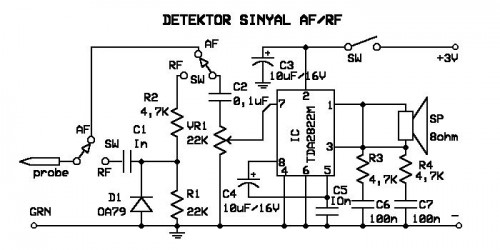
A signal detector circuit designed for detecting signals in both audio frequency (AF) and radio frequency (RF) ranges. This series is compact and straightforward to construct. The signal detector circuit operates by utilizing a combination of components such as diodes,...
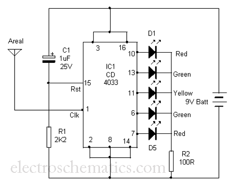
This is a simple tool designed to measure the level of radiation emitted by electrical or electronic devices. The circuit utilizes LEDs to create a running light pattern when it detects electromagnetic radiation from a source. It can detect...