
Battery-powered fluorescent lamp circuit 1

The battery-powered fluorescent lamp circuit serves as an efficient solution for providing illumination during power outages. The core component, a boosting transformer (T), is essential for stepping up the low voltage from the battery to the high voltage required to excite the fluorescent tube (E). The use of an inductive feedback oscillator allows the circuit to maintain a consistent oscillation frequency, ensuring stable operation of the fluorescent lamp.
The transistor (V7), specifically the 2SD88 type, functions as a switching element within the circuit. It controls the flow of current through the transformer, enabling the generation of the necessary high-voltage output. The inclusion of high-power silicon diodes ensures that the circuit can handle the increased current without failure, contributing to the reliability of the system.
For the transformer construction, the choice of a ferrite core with a cross-sectional area of 5mm is critical for optimizing the magnetic coupling and efficiency of the transformer. The winding of the transformer should be done using 0.22mm high-strength wire, which allows for a sufficient number of turns (approximately 20) to achieve the desired inductance. Care must be taken to maintain consistent winding practices to ensure that the inductance values are accurate and that the transformer functions effectively.
The circuit's simplicity facilitates ease of troubleshooting. If the fluorescent lamp does not illuminate, adjustments to the resistor (R) and capacitor (C) values may be necessary to fine-tune the brightness. Additionally, if the lamp fails to start, it could indicate a miswiring of the transformer or an issue with the coil connections. Ensuring that all connections are secure and correctly configured is essential for the circuit's successful operation.
Overall, this battery-powered fluorescent lamp circuit is a practical and efficient design for emergency lighting, combining readily available components with straightforward construction techniques to deliver reliable performance in critical situations.285 is indiscriminately using a battery-powered fluorescent lamp circuit, towns during a power outage use it as a temporary emergency according to the invention. Transistor V 7 , the boosting transformer T, coil I, L:., And a capacitor c-. ~ G composed of inductance feedback oscillator oscillator, an oscillating voltage boosted line indiscriminately L. After opening pressure direct contact is added to both ends of the fluorescent tube E, E lamp excitation light.
VT use 2SD88 Type and other high-power three silicon diodes, p 50 can. E is sw Chan fluorescent tube.. (; Available 6V, 41h maintenance-free battery boost variable voltage regulator T homemade needs: choice of cross-sectional area of mm 5mm of the E type ferrite core,/- -f ,. are made of high-strength wire 0 of 22mm. wound, L.,, double the backbone and about 20 smack, tap should pay attention to the end of the same name,.
about 2/0-250 dish. H behaved relatively simple circuit without trial Bute, power that can work properly. close the Jf off S, E sweet tube that is able to light up, if too bright enough town to appropriately adjust the value R., C and C until the station almost brightness requirements such as E lamp is not lit, indicating that power hoof no start-up, it may be wrong end of the coil of the same name, as long as the coil L. or, at both ends of the head of Sh :) -. That BU-cho.
Related Circuits

The circuit design involves a circular operational amplifier (op-amp) configuration that functions as a second-order low-pass and high-pass filter. The low-pass filter operates within a frequency range of 20 to 250 Hz, while details regarding the high-pass filter are...

To initiate the timing process, there are two options available: either connect the START point to ground (GND), in which case the timer activates when connected to the voltage supply, or employ a switch to start the timer. The timing...
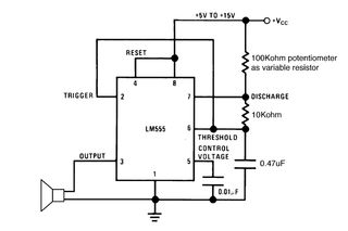
Setting the 555 timer in astable mode results in a continuous series of output pulses. The 555 timer IC, when configured in astable mode, operates as an oscillator, generating a square wave output. This configuration does not require any...
Figure 15-22 illustrates a doorbell system that consists of a monostable timing circuit, a password switch, a NAND gate circuit, and a sound output circuit. The operation of the circuit is designed such that when the password switch is...
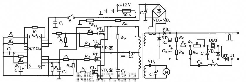
The circuit utilizes the SC3525A, a PWM silicon chip from US General Semiconductor. It features an error amplifier with an inverting input at pin 1. Pin 2 serves as the non-inverting input for the error amplifier. Pins 5 and...

Figure (a) illustrates a general inverting amplifier circuit, which includes a 100k potentiometer as a feedback resistor connected in series between the input terminal and the inverting input to compensate for the DC bias current. The potentiometer (Rp) should...