
Supply Voltage Monitor with 555 IC
The supply voltage monitor circuit utilizes the versatile 555 timer IC, which operates in a comparator mode to monitor the voltage level of the power supply. When the supply voltage exceeds a predetermined threshold, the circuit activates an output signal, typically in the form of an LED indicator. This LED will illuminate, providing a visual indication that the power supply is functioning properly.
The circuit can be configured with a voltage divider network to set the reference voltage against which the supply voltage is compared. Resistors R1 and R2 form this voltage divider, and the values can be adjusted to set the desired threshold level. The output of the 555 timer can be connected to a transistor for driving larger loads, such as an alarm or additional indicators, enhancing the circuit's functionality.
Additionally, the 555 timer can be powered by the same voltage it is monitoring, making it a self-sufficient solution. The design should also incorporate protective components, such as Zener diodes or fuses, to safeguard against overvoltage conditions. This ensures that the circuit remains operational and reliable under varying conditions.
In summary, this supply voltage monitor circuit provides an effective means of ensuring that power supply levels remain within acceptable limits, thus preventing potential damage to connected devices and enhancing overall system reliability.This is a supply voltage monitor circuit, an indicator to show if the power supply is in good condition. Designed using the IC 555 timer, this circuit will.. 🔗 External reference
Related Circuits
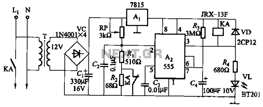
This circuit is applicable in refrigerators and other protective devices. It employs a 7815 three-terminal voltage regulator integrated circuit and an NE555 timer IC configured as a one-shot circuit for delay control. When the voltage drops below 180V, relay...
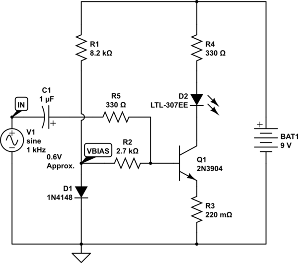
The goal is to take the voltage output from a 3.5mm audio jack and use it to light up an LED based on the audio voltage levels. The left audio channel will be connected to the base of a...
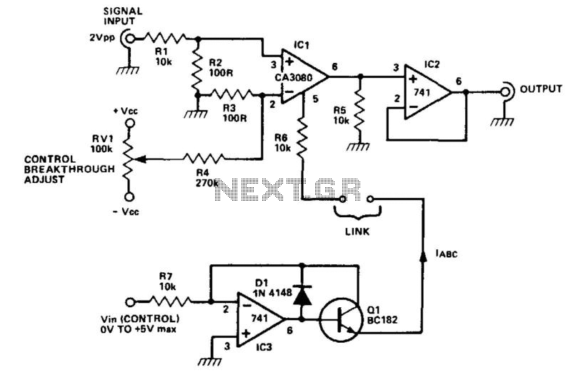
The CA3080 can be utilized as a gain-controlling device. The input signal is attenuated by resistors R1 and R2 so that a 20 mV peak-to-peak signal is applied to the input terminals. If this voltage exceeds a certain threshold,...

Transformerless Power Supply Circuit Diagram. The selection of the dropping capacitor and the circuit design requires technical knowledge and practical experience to achieve the desired voltage and current. The transformerless power supply circuit is a compact and efficient solution for...
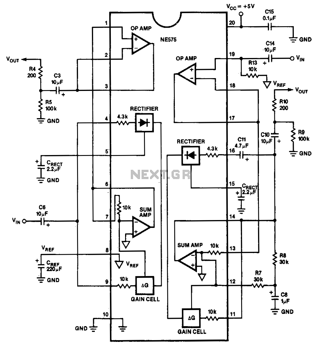
The NE575 is a dual-gain control circuit designed for low voltage applications. Channel 1 acts as an expander, while Channel 2 can be configured for expander, compressor, or automatic level controller (ALC) applications. The NE575 dual-gain control circuit is specifically...

The sensor/monitor depicted in the diagram activates the host system upon detecting infrared (IR) signals. It consumes very little supply current, allowing it to remain continuously operational in devices such as notebook computers or PDAs. The ultra-low current drain,...