
HIGH VOLTAGE PULSE SUPPLY
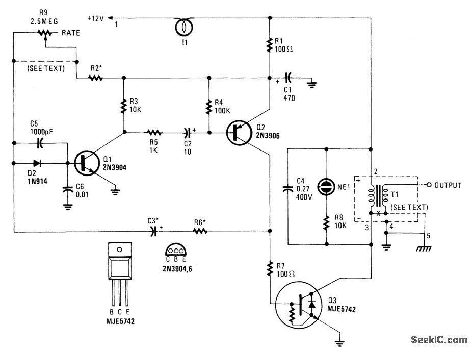
The high-voltage pulse supply circuit is designed to generate high-voltage pulses suitable for various applications, including ignition systems and testing equipment. The core of the circuit is a multivibrator configuration formed by transistors Q1 and Q2, which alternately turn on and off, creating a square wave signal. This signal is shaped by the resistors R1 to R6 and the capacitors C1, C2, C3, C5, and C6, which determine the timing characteristics and stability of the multivibrator.
Resistor R9 plays a crucial role in adjusting the frequency of the output pulses. By varying the resistance, the pulse repetition rate can be fine-tuned to meet specific operational requirements. R2 is selected to limit the maximum frequency to 20 Hz, ensuring that the circuit operates within safe limits while still providing sufficient pulse output for the intended application.
The inclusion of lamp I1 as a current limiter is a critical safety feature. It prevents excessive current from flowing through the circuit, protecting sensitive components from damage. In scenarios where a fixed pulse rate is required, R9 can be omitted, and R2 adjusted accordingly to establish a stable output.
Transistor Q3 acts as an amplifier and switch, providing the necessary power to drive T1, the automotive ignition coil. This coil is responsible for stepping up the voltage to the desired 30 kV output. The high voltage generated can be utilized for various applications, including ignition systems in internal combustion engines or high-voltage testing.
The NE1 component serves as a pulse indicator, providing visual feedback on the circuit's operation. This feature is particularly useful for troubleshooting and ensuring that the circuit is functioning as intended.
Given the high voltage capabilities of this circuit, it is imperative to adhere to strict construction techniques and safety protocols. Proper insulation, secure connections, and protective enclosures should be employed to mitigate the risks associated with high-voltage operation. Users must be trained and equipped with the necessary safety gear when working with or around this circuit to prevent electrical hazards.This high-voltage pulse supply will generate pulses up to 30 kV. Q1 and Q2 form a multivibrator in conjunction with peripheral components R1 through R6 and C1, C2, C3, C5, C6, and D2. R9 adjusts the pulse repetition rate. R2 should be selected to limit the maximum repetition rate to 20 Hz. I1 is a type 1156 lamp used as a current limiter. R9 can b e left out and R2 selected to produce a fixed rate, if desired. Q3 serves as a power amplifier and switch to drive T1 (an automotive ignition coil). NE1 is used as a pulse indicator and indicates circuit operation. Because this circuit can develop up to 30 kV, suitable construction techniques and safety precautions should be observed. 🔗 External reference
Related Circuits
Improve the power factor (PF) to enhance energy conservation in electrical equipment. With advancements in electronic technology, high-frequency active power factor correction (PFC) technology has been increasingly applied across various power systems. The switching power supply of large-screen color...
A simple transformerless power supply circuit with a diagram and schematics that provides a 5 volts DC output. This is a low-cost, low-current power supply circuit suitable for simple applications such as powering an LED. The transformerless power supply circuit...
A switching power supply that has an output voltage significantly lower than its input voltage exhibits a unique characteristic: the current drawn from the supply is less than the output current. However, the input power (UI) is, naturally, greater...
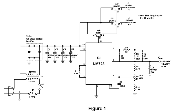
Activated this and inadvertently destroyed several 2N3055 transistors by shorting the emitters to ground. In all cases, the transistors opened up, and no damage to the emitter occurred in any transistor. The alternative circuit in Figure 2 will provide...
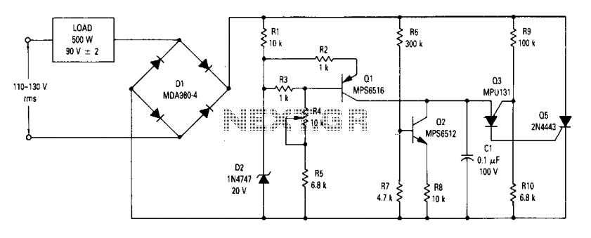
The circuit is an open-loop RMS voltage regulator designed to deliver 500 watts of power at 90 V RMS, maintaining good regulation within an input voltage range of 110-130 V RMS. When the input voltage is applied, capacitor C1...
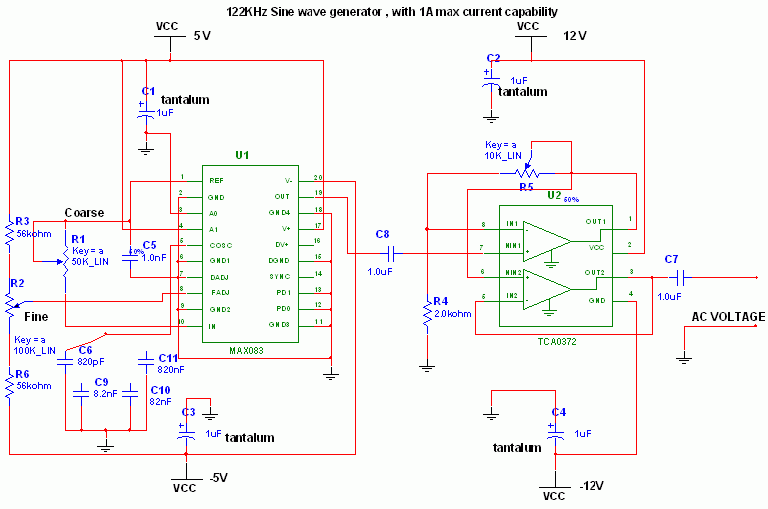
This circuit utilizes the versatile MAX038 function generator. While some advanced features of this IC are disabled in this configuration, it is capable of generating sine, triangle, and square waves by adjusting the A0 and A1 pins (refer to...