
BATTERY SIMULATOR CIRCUIT
The battery simulator circuit is a crucial tool for testing and developing battery chargers without the need for an actual battery. This simulator provides a controlled environment to replicate the charging and discharging characteristics of a battery, allowing engineers to evaluate the performance of their charger designs effectively.
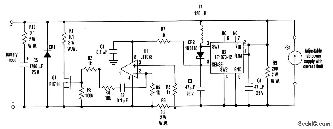
In the circuit, the operation is divided into two modes: Discharge and Charge. In Discharge mode, the simulator acts as a passive load, drawing power from the current-limited lab power supply (PS1). This mode is beneficial for testing the charger’s ability to handle load conditions without the risk of damaging a real battery.
During Charge mode, the simulator actively mimics the behavior of a battery being charged. The charge current is routed through the battery input terminals, where the voltage across R8 is monitored. The operational amplifier U1 amplifies this voltage, providing feedback to control the shunting action of transistor Q1. This feedback loop ensures that the charge current remains within safe limits and that the voltage from PS1 is stable.
The inclusion of components such as U2, L1, CR2, C3, and C4 is essential for generating a reliable internal power supply. This 12-V supply is critical for the proper functioning of U1 and Q1, ensuring that the circuit operates efficiently across the specified voltage range of PS1.
Diode CR1 plays a vital role in protecting the circuit from potential damage due to reverse polarity connections, which could occur if the simulator is inadvertently connected incorrectly. The design also considers the thermal management of transistor Q1, necessitating a heat sink to dissipate heat generated during operation, particularly when handling high charge currents.
Resistor R1 provides a means to measure the charge current, allowing for real-time monitoring of the charging process. Additionally, R10 and C5 emulate the AC characteristics of a battery, ensuring that the simulator can accurately represent the dynamic behavior of real batteries during charging and discharging cycles.
Overall, this battery simulator circuit is an invaluable asset for engineers working on battery charger development, providing a versatile and safe testing platform.When developing a battery charger, using a real battery might be inconvenient. The battery simulator circuit described here is an alternative. The battery input positive and negative terminals should be connected in place of the battery in the charger circuit. Also, a current-limited lab-type power supply must be connected to the simulator circuit (as shown). In Discharge mode, the battery simulator uses the current-limited lab power supply PS1 as a source, and the simulator is inactive. In Charge mode, charge current is forced through the battery input terminals. Low voltage that develops across R8 is amplified by U1 and causes Q1 to shunt the charge current while maintaining the power-supply (PS1) voltage.
U2, L1, CR2, C3, and C4 produce an internal 12-V power supply that is required to operate U1 and drive Q1. The PS1 voltage range is 1. 5 to 15 V. Diode CR1 protects the circuit from reverse polarity and is needed if the maximum charge current is too high for the body diode of Q1 (Q1 must be heat sunk).
R1 is a sense resistor for measuring the charge current. R10 and C5 simulate the ac characteristics of the battery. 🔗 External reference
Related Circuits
This circuit can be used to operate an electric strike or an electromagnetic lock on a door. It is not the door being opened/closed, but a small electromagnetic strike which unlocks the door. The opener has the following features...

This circuit is a graphic equalizer that can be built with a low component count and is controlled using the LA3600 single IC chip. The internal design of the chip utilizes a transistor gyrator circuit, with connections to external...
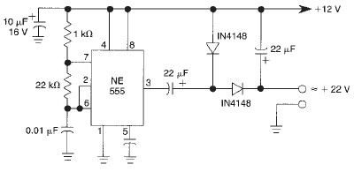
This voltage doubler circuit utilizes a 555 timer integrated circuit configured as an astable multivibrator. It can deliver a maximum output current of 50mA; exceeding this limit will result in a reduction of the output voltage. The actual output...
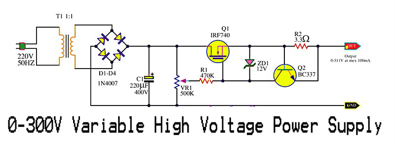
This is a variable high voltage DC power supply circuit that allows for customization of the output voltage ranging from 0 to 311V DC. It includes a current limit protection feature set at approximately 100 mA. The power MOSFET...
The ability amplifier has remained functional since it was first introduced in 2002. It is not broken, so there is no reason to fix it. The accompanying photo shows a well-assembled board (known as M27). Utilizing TIP35/36C transistors, the...
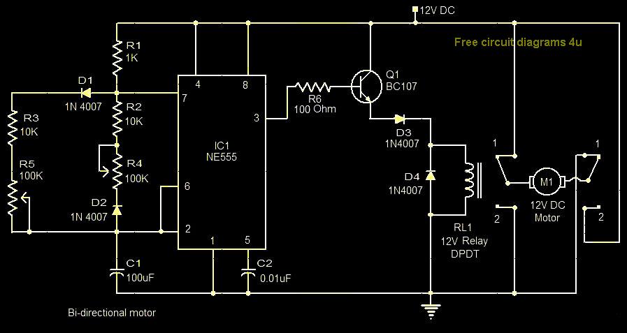
This circuit illustrates a bi-directional motor control circuit utilizing the NE555 integrated circuit (IC). Features include a 12V DC power supply, with the IC employed to control relay RL1. The bi-directional motor control circuit designed with the NE555 IC allows...