
Battery simulator provides current limiting

A constant-voltage active load circuit is designed to simulate the behavior of a battery during the charging process, making it an essential tool for testing and calibrating battery chargers. The circuit utilizes a variable potentiometer (PV) to set the desired load voltage between 5V and 35V, allowing for the emulation of different battery voltages ranging from 6V to 32V. This versatility is crucial for engineers who need to assess the performance of battery chargers under various conditions.
The current-limiting feature is implemented through the use of switch S1, which when opened, activates the protection mechanism. This mechanism is vital for preventing excessive current that could damage the charger or the load. The accompanying LED indicator serves as a visual cue, alerting the user when the current limit is reached, thus indicating that the circuit has transitioned from its constant-voltage mode.
To accurately simulate the dynamic response of a battery, the circuit can incorporate multiple electrolytic capacitors. These capacitors allow for the bidirectional flow of current pulses, mimicking the charging and discharging behavior of real batteries. However, caution must be exercised as a large capacitive load can lead to oscillations, which may complicate the feedback loop necessary for stable operation. In scenarios where instability occurs, switch S2 can be employed to disconnect the capacitors, thereby mitigating the oscillatory behavior.
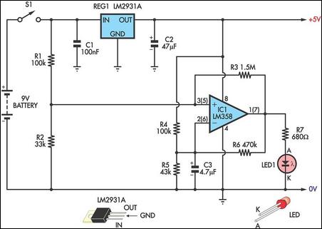
For situations where closed-loop compensation proves challenging, it is recommended to explore compensation strategies that do not rely on capacitors. This approach can help maintain stability in the circuit while still providing the necessary load characteristics for effective battery charger testing. Overall, the design of this constant-voltage active load circuit emphasizes flexibility, safety, and reliability, making it an indispensable tool in the field of battery charger development and testing.A constant-voltage active load can perform as a battery during the charge cycle. You can set the load voltage from 5 to 35V by using potentiometer PV and thus can simulate batteries ranging from 6 to 32V. In testing a battery charger (during design or for calibration purposes), a current-limiting function is a desirable feature; you e
nable this protection feature by opening S1. The LED lights if the current reaches the limit. This feature lets you know when the circuit goes out of its constant-voltage operating mode. To simulate the dynamic behavior of a battery, you can connect several electrolytic capacitors. With the addition of these capacitors, current pulses can flow bidirectionally between the load and the battery charger. In some cases, a large capacitive load could cause oscillations, making it difficult to provide loop compensation for stable closed-loop operation.
In case of such instability, switch S2 provides capacitor disconnection. If you encounter closed-loop compensation problems, try to compensate without using capacitors. (DI #2065) 🔗 External reference
Related Circuits
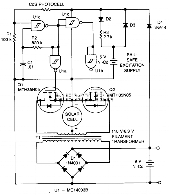
The circuit charges a 9-V battery at approximately 30 mA per input ampere at 0.4 V. U1, a quad Schmitt trigger, operates as an astable multivibrator to drive push-pull MOSFET devices Q1 and Q2. Power for U1 is derived...
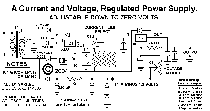
This circuit employs a rotary switch to select various current ranges, as using a potentiometer is not practical for lower resistance and high current ranges. However, a potentiometer can be utilized for lower current ranges, with the lowest switch...
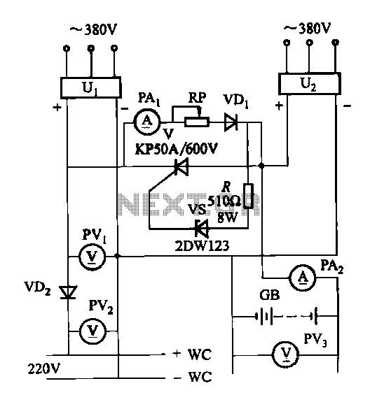
The DC panel battery is commonly utilized in power plants and substations within DC systems. To enhance the safety and reliability of the current system, an uninterrupted power supply switching circuit may be implemented. This circuit includes components such...
This circuit indicates the remaining battery life by varying the duty cycle and flash rate of an LED as the battery voltage decreases. It indicates five battery conditions: (1) a steady glow indicates that the battery is healthy; (2)...
This is a simple NiCd battery charger powered by solar cells. A solar cell panel or an array of solar cells can charge a battery at more than 80% efficiency. The described circuit functions as a basic NiCd battery charger...
When the door is opened, SW1 closes, powering the circuit and turning on the lamp. C1 begins to charge slowly through R1, and when the voltage at pins #2 and #6 of IC1 reaches 2/3 of the supply voltage,...