
Solar cell battery charger circuit

The described circuit functions as a solar-powered battery charger for a 9-V battery, utilizing a combination of a Schmitt trigger, MOSFETs, and a transformer-based rectification system. The key component, U1, is configured as an astable multivibrator, generating a square wave output that alternates between high and low states. This oscillation drives the MOSFETs Q1 and Q2 in a push-pull configuration, allowing for efficient switching and control of the power delivered to the load.
The power supply for U1 is sourced from the 9-V battery, which is essential for the operation of the Schmitt trigger and ensures that the control circuit remains functional during the charging process. Diode D4 serves to isolate the power supply for U1 from the output, protecting the circuit from potential back-feeding and ensuring stable operation.
The solar cell provides the necessary input power for the MOSFETs, enabling them to switch on and off rapidly at the frequency set by the resistor R2 and capacitor C1. The choice of 180 Hz for the multivibrator frequency is optimized for the characteristics of the 6.3-V filament transformer, T1, which steps down the voltage for rectification. The secondary winding of T1 feeds into a full-wave bridge rectifier composed of diode D1, converting the alternating current (AC) output from the transformer into direct current (DC) suitable for charging the 9-V battery.
To enhance the reliability of the system, a small Ni-Cad battery is included as a fail-safe measure. This battery provides a backup power source for the circuit, ensuring that it can recover and continue functioning if the primary 9-V battery is fully depleted. The incorporation of a CdS photocell adds an additional layer of protection; it monitors ambient light levels and disables the oscillator when darkness is detected. This feature helps conserve the charge in the fail-safe battery during shipping, storage, or extended periods without light, thus prolonging the operational lifespan of the system.
Overall, the circuit design effectively combines renewable energy sources with robust battery management features, making it suitable for applications where reliable battery charging is essential.The circuit charges a 9-V battery at about 30 mA per input ampere at 0.4 V. Ul, a quad Schmitt trigger, operate as an astable multivibrator to drive push-pull TMOS devices Ql and Q2. Power for Ul is derived from the 9-V battery via D4; power for Ql and Q2 is supplied by the solar cell.
The multivibrator frequency, determined by R2-C1, is set to 180 Hz for maximum efficiency from a 6.3-V filament transformer, Tl. The secondary of the transformer is applied to a full wave bridge rectifier, Dl, which is connected to the batteries being charged.
The small Ni-Cad battery is a fail-safe excitation supply to allow the system to recover if the 9-V battery becomes fully discharged. A CdS photocell shuts off the oscillator in darkness to preserve the fail-safe battery during shipping and storage, or prolonged darkness.
Related Circuits
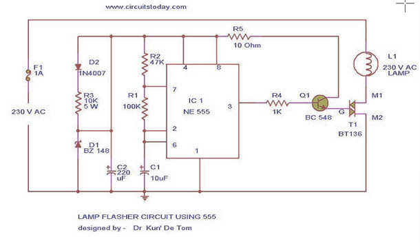
This circuit diagram represents a lamp flasher powered by mains electricity. It is capable of flashing lamps with a maximum power of 200 Watts at user-defined rates. The NE555 integrated circuit is configured as an astable multivibrator, generating the...

This circuit is designed to charge between one and twelve NiCd cells using a car battery. With switch S1 set to the normal position, it is capable of charging up to six cells. The circuit operates by utilizing a car...
One of the critical components is a PWM speed controller, allowing for fine speed adjustments instead of just an "on" mode that runs at full power. This is important for safety. A basic stamp microcontroller was purchased, which includes...
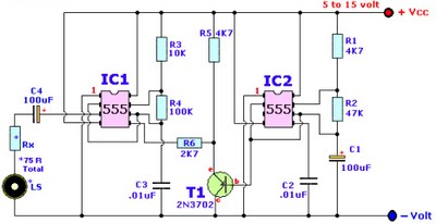
Browse home alarm circuit explanation latest schematic siren wailing with latest Wailing Alarm Siren circuit schematic with explanation. The loudspeaker LS and the resistor marked Rx should be together 75 ohms. If a standard 8-ohm speaker is used, then...

This circuit is designed as a low dropout charger using a MOSFET as the pass element; however, it does not incorporate current limiting. The circuit diagram illustrates a straightforward design. It utilizes Q3 and a Schottky diode to isolate...
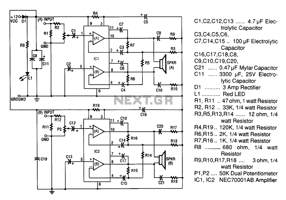
A 20W + 20W stereo amplifier comprises two independent 20-watt RMS amplifiers configured in a bridge arrangement. The input source is connected to a shunt voltage amplifier through resistors R1, R2, and potentiometer P1. Resistor R1 provides load resistance...