
Battery Tester For Deaf and Blind Persons
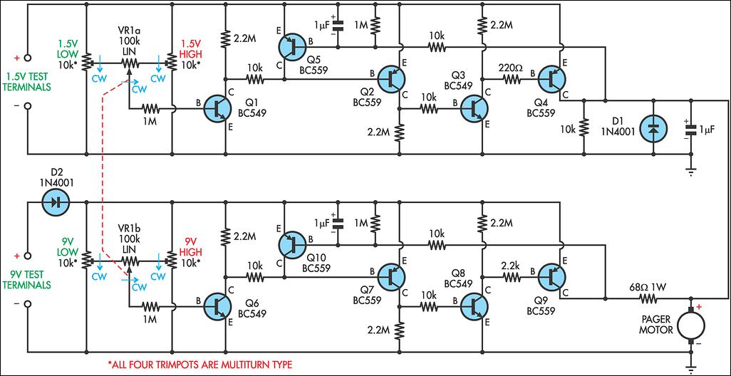
On the 1.5V side of the circuit, a resistor network comprising two 10kΩ multi-turn trimpots (VR2 & VR3) and a user control (VR1a) generates an adjustable proportion of the voltage of the tested cell. VR1a selects a division ratio between the low and high limits established by the trimpots. The resistance of VR1a is ten times larger than that of the trimpots to minimize interaction between their settings. The voltage from this resistance network feeds into a combined threshold detector and current amplifier formed by transistors Q1 to Q4 and their associated components. When the threshold (approximately 0.6V) is surpassed, the pager motor is activated, causing the battery tester to vibrate. During operation, VR1 is initially set to its fully counter-clockwise position, then a cell is connected. If the cell's voltage exceeds the 1V low threshold determined by the 1.5V LOW trimpot (VR2), the tester will vibrate. Rotating VR1 clockwise reduces the voltage applied to the threshold detector until it falls below the threshold, at which point the pager motor turns off. The angle of rotation of VR1 indicates the voltage of the battery. VR1 is equipped with a pointer knob to facilitate tactile feedback regarding the angle of rotation.
The design ensures that the pager motor turns off rather than on, enabling the voltage of the battery to be sampled under load conditions. This provides a more accurate representation of the battery's state compared to its open-circuit voltage. To enforce that the user rotates VR1 clockwise during testing, the circuit is configured so that once vibration ceases, it cannot be reactivated by rotating VR1 counter-clockwise. This eliminates potential user confusion resulting from circuit hysteresis. This feature is implemented by transistor Q5, which drives the base of Q2 high if Q4 stops conducting strongly. A 1µF capacitor between the base and emitter of Q5 ensures it turns off when power is initially applied, allowing Q4 a chance to conduct. A parallel 1MΩ resistor discharges the 1µF capacitor when power is removed, resetting the circuit.
To prevent the pager motor from being driven through the base-emitter junction of Q5, the base of Q5 connects to the collector of Q4 via a 10kΩ resistor. An additional 10kΩ resistor in parallel with the pager motor guarantees that Q5 activates when Q4 deactivates. The 9V test circuit mirrors the 1.5V circuit, with a 68Ω 1W resistor limiting current through the motor to prevent over-driving at higher voltages. A series diode protects the 9V circuitry against reverse polarity. While a diode cannot be used on the 1.5V side due to excessive voltage drop, it is unnecessary since 1.5V is below the reverse breakdown voltage of the employed transistors. A 1µF capacitor across the pager motor smooths the load, ensuring consistent measurements. A 1N4001 diode across the pager motor clips any back-EMF generated.
A D-cell holder and an AA-cell holder connected in parallel serve as the 1.5V test terminals, while the 9V test terminals consist of standard 9V snap studs secured to the enclosure. To calibrate the battery tester, begin with VR1 fully counter-clockwise. First, adjust the 1.5V LOW trimpot by turning it fully counter-clockwise, then apply 1.0V to the 1.5V test terminals and slowly rotate the trimpot clockwise until vibration just stops. Next, set VR1 fully clockwise and adjust the 1.5V HIGH trimpot similarly with 1.6V applied to the 1.5V test terminals. Due to minor interaction between the low and high settings, repeat the adjustment of the 1.5V LOW trimpot. The 9V side of the circuit is calibrated for a range from 6.0V to 9.6V.
To test a battery, rotate VR1 fully counter-clockwise before connecting the battery to the appropriate test terminals (1.5V or 9V). If the device does not vibrate, the battery is completely discharged. If it vibrates, rotate VR1 slowly clockwise until the device ceases to vibrate. The position of VR1 then indicates the condition of the battery under test.Many blind and deaf-blind persons use portable electronic devices to assist their everyday lives but it is difficult for them to test the batteries used in this equipment. Talking voltmeters are available but there is no equivalent usable by deaf-blind persons. This battery tester uses vibration and a user-settable control to enable blind and deaf -blind persons to test both ordinary and rechargeable AAA, AA, C, and D cells and 9V batteries. For ease of use and maintenance the device is powered by the battery under test. The design is dominated by the fact that the pager motor will operate down to only 0. 7V. With a 0. 3V drop from the switching transistor, a weak cell, at 1. 0V, will only just operate the motor. This means that the 1. 5V cell sensing circuitry cannot be isolated from the 9V test terminals using steering diodes - they would introduce too great a voltage drop. The solution was to duplicate the level sensing circuitry for each set of test terminals. On the 1. 5V side of the circuit, a resistance network consisting of two 10kO multi-turn trimpots (VR2 & VR3) and user control VR1a produces an adjustable proportion of the voltage of the cell under test.
VR1a selects a division ratio between the low and high limits set by the trimpots. The resistance of VR1a is 10 times larger than the resistance of these trimpots to minimise the interaction between their settings. The voltage from the resistance network is applied to a combined threshold detector and current amplifier formed by Q1 to Q4 and associated components.
When the threshold (about 0. 6V) is exceeded the pager motor is energised, causing the battery tester to vibrate. In use, VR1 is first set to its fully counter-clockwise position, then a cell is connected. If the cell`s voltage exceeds the 1V low threshold set by the 1. 5V LOW trimpot (VR2), the battery tester will vibrate. Rotating VR1 clockwise applies a progressively lower voltage to the threshold detector until a point is reached when the threshold is no longer exceeded and the pager motor switches off. The angle of rotation of VR1 then indicates the voltage on the battery. VR1 is fitted with a pointer knob to make the angle of rotation easy to feel. Having the pager motor switch off rather than switch on ensures that the voltage of the battery is sampled while it is supplying the load of the pager motor.
This gives a more accurate indication of the state of the battery than its open-circuit voltage. To ensure that the user turns VR1 clockwise during the test, the circuit is designed so that once vibration has ceased, it cannot be made to start again by rotating VR1 counter-clockwise. This also eliminates any possibility of user confusion arising from any hysteresis in the circuit. This feature is implemented by Q5, which forces the base of Q2 high if Q4 ceases to conduct strongly.
A 1 µF capacitor between the base and emitter of Q5 forces it off when power is first applied, to give Q4 a chance to conduct. The parallel 1MO resistor discharges the 1 µF capacitor when power is removed, to reset the circuit. To prevent the pager motor being driven through the base-emitter junction of Q5, the base of Q5 is connected to the collector of Q4 via 10kO resistor.
Another 10kO resistor is connected in parallel with the pager motor to ensure that Q5 switches on when Q4 switches off. The 9V test circuit is similar to the 1. 5V circuit. A 68O 1W resistor limits the current through the motor to prevent it from being over-driven by the higher voltage.
In addition, there is a series diode to protect the 9V circuitry against reverse polarity. A diode is not possible for the 1. 5V side of the circuit because it would introduce too great a voltage drop; fortunately, it is also unnecessary since 1. 5V is below the reverse breakdown voltage of the transistors used. The 1 µF capacitor across the pager motor smoothes the load provided by the motor so that measurements made by the circuit are consistent from one trial to another.
The 1N4001 diode across the pager motor clips any back-EMF generated by the motor. A D-cell holder and an AA-cell holder connected in parallel were used for the 1. 5V test terminals. The 9V test terminals are the studs from a standard 9V snap screwed to the box. To calibrate the battery tester, start with VR1 fully counter-clockwise. First adjust the 1. 5V LOW trimpot by turning it fully counter-clockwise, then apply 1. 0V to the 1. 5V test terminals and turn the trimpot slowly clockwise until vibration just ceases. Now turn VR1 fully clockwise and adjust the 1. 5V HIGH trimpot similarly with 1. 6V applied to the 1. 5V test terminals. There is a small amount of interaction between the low and high settings, so repeat the adjustment of the 1. 5V LOW trimpot. Similarly, calibrate the 9V side of the circuit for a range of 6. 0V to 9. 6V. To test a battery, rotate VR1 fully counterclockwise before connecting the battery to the appropriate set of test terminals (1.
5V or 9V). If the device does not vibrate, the battery is completely dead. Otherwise, rotate VR1 slowly clockwise until the device just ceases to vibrate. The position of VR1 then shows the condition of the battery under test. 🔗 External reference
Related Circuits
The rechargeable Li-ion battery charger circuit operates with a limited current charging and constant voltage. The charging current flows from the rectified voltage of the transformer through the transistor T1, diode D5, resistor R2, and back to the battery....
Field-effect transistors (FETs) are integral components found in various applications such as power sections, LCD inverters, uninterruptible power supplies (UPS), amplifiers, monitor B+ circuits, and ATX power supplies. When a FET fails, it is essential to use a meter...
This is a battery charger circuit that has the advantage of automatically disconnecting the battery when charging is complete. The voltage sensor used in this circuit is the LM301 IC, which serves to disconnect the battery when the charging...
All car batteries require a 12V battery charger, which also applies to marine, RV, and power sports batteries. The high-efficiency lead-acid batteries available today necessitate more effective charging techniques. The battery charger is a crucial tool for prolonging battery...

A motorcycle or boat battery that is not needed over the winter is typically charged before being stored for the season, during which it remains unused for several months. This inactivity can lead to the accumulation of lead sludge,...
Switch mode circuits can implement a lead acid battery charger more efficiently. It can be constructed using the bq24105 battery charger controller. Switch mode power supplies (SMPS) are widely recognized for their efficiency and compactness, making them suitable for applications...
Warning: include(partials/cookie-banner.php): Failed to open stream: Permission denied in /var/www/html/nextgr/view-circuit.php on line 713
Warning: include(): Failed opening 'partials/cookie-banner.php' for inclusion (include_path='.:/usr/share/php') in /var/www/html/nextgr/view-circuit.php on line 713