
mosfets tester
Field-effect transistors (FETs) play a crucial role in various electronic systems, functioning as switches or amplifiers in circuits. Their operation relies on voltage control, making them ideal for applications where efficiency and speed are paramount. The testing process for FETs is vital for ensuring reliability in electronic devices. When a FET is suspected to be faulty, the testing method employed can greatly affect the accuracy of the diagnosis.
Standard multimeters can measure resistance and voltage, but they may not provide sufficient detail when it comes to assessing FET functionality. Specialized FET testers offer advanced features, including automatic pin identification and dedicated testing modes for different FET types, streamlining the testing process. These testers often include visual indicators, such as LEDs, to provide immediate feedback on the FET's condition, simplifying the troubleshooting process.
The use of IC sockets during testing serves to enhance the reliability of the measurements. By securely holding the FET in place, the sockets not only reduce the likelihood of accidental shorting but also allow for easier handling, especially in tight spaces where precision is essential. The inclusion of a DPDT switch in the design allows for quick transitions between testing modes, accommodating different FET types without the need for extensive reconfiguration.
In summary, the effective testing of FETs is critical in maintaining the functionality of electronic devices. By utilizing specialized testers and incorporating IC sockets, the testing process becomes more efficient and reliable, leading to more accurate assessments of FET health and performance.FETs can be found in the power section, LCD inverter, UPS, Amplifier, Monitor B+ and S-correction circuit, ATX power supplies and etc. When this component fails, one has to use a meter to test it to check if it is good, shorted, openor leaky.
The meters can be a normal multimeter, specialize FET tester like the Peak Atlas Tester, Sencore Cricket Tester, B & K transistor tester and etc. The specialize testers are expensive and most of it could helps you to automatically identify the pins of the FET (gate, drain or source). If you use a normal multimeter, you have to identify the pins on your own. Assuming if you do not know the pin out of the FET, you can always check from the data book or even from the internet.
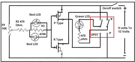
If you want more information about FETs, you can click HERE to visit Wikipedia website. The IC sockets are good for holding the FET during testing time. We use just three pins of each socket for the Gate (G), Drain (D) and Source (S). One socket is for N-CHANNEL FET and the other one for P-CHANNEL FET. The DPDT switch is good for changing the mode of tester from testing N to P-CHANNEL FET. Another advantage of this tester is that if you have been using multimeter to test on FETs, you will find that our hands is too big for the small FET pins (TO- 92 Case). Thus by inserting the small FETs into the IC socket, you will eliminate the error of one finger touching on another pin during testing time using the multimeter.
If the FET is shorted one of the red LED will lit. In order to confirm that the FET under test is good even if you increase the potentiometer to maximum the red LED should not lit otherwise the FET is bad or leaky. For a good FET the green LED will light up. 🔗 External reference
Related Circuits
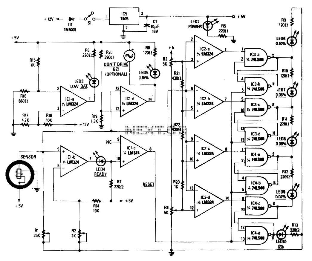
When power is applied to the circuit, the heater coil in the sensor is energized by the 5-V output of IC5, a 7805 voltage regulator. Breathing into the sensor with alcohol on one's breath will lower the sensor's resistance;...
A DC capacitor tester circuit diagram utilizing a 555 timer is presented. The tester includes a pulse generator, a one-shot circuit, a DC amplifier, and a meter indication circuit. It is capable of measuring capacitors ranging from nanofarads (nF)...
Use this circuit to test if the light coming from your 40kHz IR emitter is really emitting the right frequency. The schematic says to use a GP1U5X IR module, but probably any 40kHz detector module will work. I used...
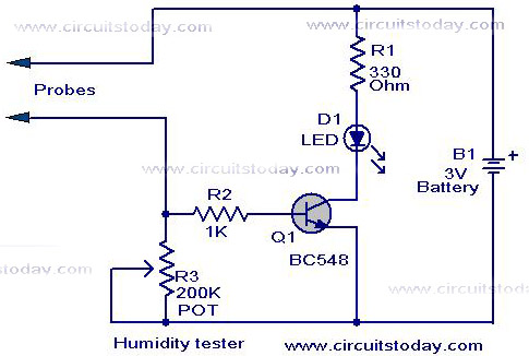
A simple humidity tester circuit using only an LED, a transistor, and a few resistors is explained with a clear circuit schematic. The humidity tester circuit is designed to provide a visual indication of humidity levels using basic electronic components....
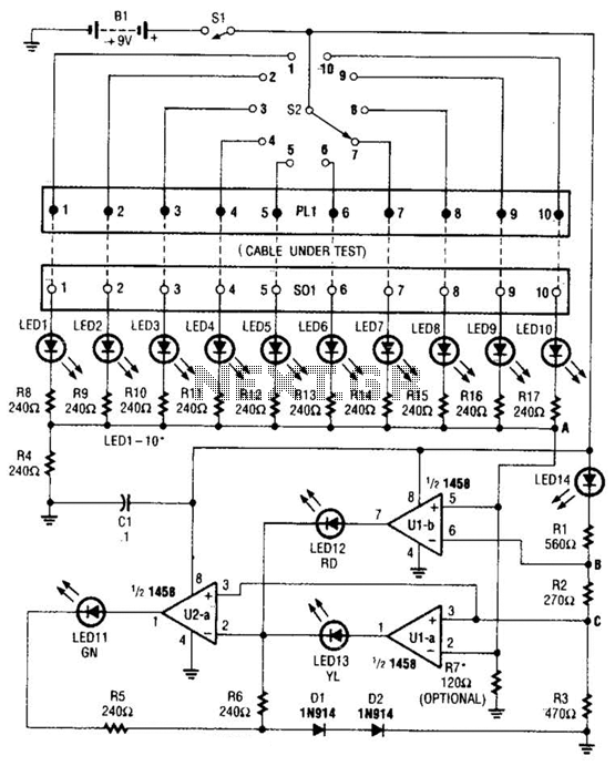
The cable tester utilizes two operational amplifiers (op-amps) configured as window comparators to detect short or open circuit conditions. A third op-amp comparator is employed to indicate a properly functioning circuit, meaning it is neither open nor shorted. Colored...
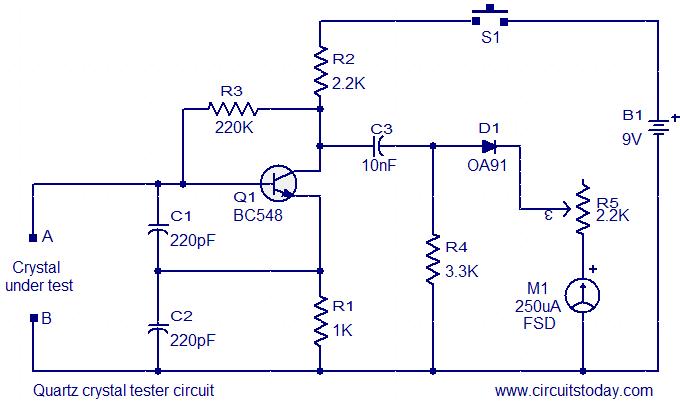
This is a straightforward and cost-effective circuit designed for testing quartz crystals. A Colpitts oscillator is employed using transistor T1. When the crystal is connected between terminals A and B, the circuit generates high-frequency oscillations. These oscillations will only...