
Single Cell Lithium-ion battery charger
The TL431C voltage stabilizer becomes active at the final charging voltage. As the voltage increases, current begins to flow through the IC, reducing the current through T2. The final charging voltage is set by the resistor divider R4, R5, and R6, with R5 used for precise voltage adjustment. The TL431C increases current flow between terminals C and A when the input voltage reaches 2.5V. Capacitor C2 and resistor R7 ensure the stability of the controller.
During the constant voltage charging phase, LED1 turns off (T2 closes), and LED2 turns on, indicating charging status. When LED2 is lit, the battery is over 70% charged. Leaving the battery in the charger allows it to reach 100%, with the charging current gradually dropping to zero. Lithium-ion batteries do not exhibit a memory effect, so partial discharging and charging do not cause harm.
The charger can be implemented on a printed circuit board, and transistor T1 should be mounted on a heatsink (DO1) due to the minimal power loss on T1. The circuit uses low-current LEDs (2mA). To revive the charger, the battery voltage should be precisely 4.2V (or 4.1V for older batteries). If the voltage is incorrect, R5 can be replaced with a resistor of 180, 200, 240, or 270 Ohms. Output voltage should be measured with high-quality equipment, as cheap devices may not provide accurate readings. The final voltage should be 4.2V, and if it drops below 4V under load, the charging current can be adjusted by changing resistor R2, with a resistance of 2.2 Ohms resulting in a charging current of around 220mA.
Batteries can be charged in series by adjusting resistors R4 and R5 to stabilize the output voltage at 2x or 3x 4.2V, depending on the number of cells. It is advisable to charge each battery separately to prevent overcharging. Lithium-ion batteries require careful handling, with recommended charge currents ranging from 0.1C for older types to 0.5 to 2C for newer types. Discharge currents can be several times larger.
The charging voltage for lithium-ion batteries is critical; most modern types require a charging voltage of 4.2V, while some older types may require 4.1V. Exceeding these voltages can cause irreversible damage unless the battery is equipped with an electronic protective circuit. The circuit components include resistors R1 (1 kOhm), R2 (2.2 Ohms), R3 (470 Ohm), R4 (15 Ohm, 1%), R5 (220 Ohm), R6 (22 Ohm, 1%), R7 (10 kOhm), capacitors C1 (1000 µF/25V) and C2 (100 nF ceramic), diodes D1-D4 (B250C1000), D5 (1N4001), LEDs (LED1 - Red, LED2 - Green, both at 2 mA), transistors T1 (BD675) and T2 (BC548), and the TL431C IC. The transformer specifications are 3.2 VA, 230/9V, TR EI38/13, 6-1x9.
To ensure proper charging, if the charge current exceeds the transformer's capability, LED1 will illuminate during charging, but the charger will function correctly. The described charger has shown no adverse effects on battery power when used for extended periods. The power element for voltage and current regulation is transistor T1, while diode D5 prevents discharging when the battery is connected to the charger but not to the mains. When using Darlington pairs, ensure that the transition can handle reverse voltages greater than 5V.The rechargeable Li-ion, I began to intensely interested last summer, when I managed to bring a holiday without a phone charger. After several experiments involving originated in Figure 1, which has proved. Involvement of the stage provides a limited current charging and constant voltage. Charging current from the rectified voltage of the transformer through the transistor T1, diode D5, resistor R2 and the battery back to AC power.
Current flow creates a voltage drop on R2, which opens T2. The transistor T2 controls the current through T1 - the current is regulated so that R2 was approximately constant voltage drop. The collector is connected LED1 T2, indicating the stage of charging current. Resistor R1 is deliberately chosen a relatively small resistor that flowed much more power than you need to drive T1. Most of this current then flows through LED1 and T2. LEDs because the entire phase charging current of approximately constant bright light. Involvement LED1 limits the minimum output voltage at which the circuit operates correctly at about 1 V.
Since the discharged battery voltage is still greater than 3 V, it is not at fault. Part of the circuit to stabilize the output voltage phase charging current does not apply. LED2 through the current small and poorly lit. Stabilizer TL431C to take effect in reaching the final tension. With increase of voltage the current starts to flow ICs, while the current of T2 is reduced. The final charging voltage is set divider R4, R5 and R6. Resistor R5 is used for precise adjustment of the output voltage. TL431C function circuit is very simple - increases when the input voltage of 2.5 V R, increases the current flowing between terminals C and A. The capacitor C2 and resistor R7 serves to ensure the stability of the controller. In constant voltage charging phase LED1 off (T2 is closed) and turns on LED2. It is thus very simple procedure indicated charging. When LED2 is lit, the article charged to more than 70%, and we use it. Conversely, left the article in the charger part is gradually recharged to 100% and charge current drops gradually to zero.
Given that the batteries do not have no memory effect, partial discharging and charging them with harm. The charger can be placed on a printed circuit board as shown in Figure 2 and 3 Transistor T1 affixed to a small cooler (DO1).
The components are used by the loss on T1 very small. LEDs are the types of small currents (2 mA). Reviving the charger is very simple. Mount the battery to check the output voltage should be as precisely 4.2 V (or 4.1 V for older articles). If not, replace with another R5 for resistor 180, 200, 240 or 270 Ohm. The output voltage should be measured on quality equipment, cheap devices are not sufficiently accurate; my showing at 4.14, while the output was 4.09 V.
We require a final voltage of 4.2 V, completely drop the resistor R5. Charging current to verify that the output is connected to a load, the voltage dropped below 4 V. The charging current can be adjusted by changing resistor R2. The resistance of 2.2 ohms was charging current around 220 mA. Batteries can be recharged in the series, simply adjust the resistor R4 and R5 so that the output voltage was stabilized 2x or 3x 4.2 V - the number of cells. You can also adjust the resistor R2 and to increase the charging current. Before the stabilizer (the capacitor C1) voltage must be at least 3-4 in the larger, so you need to use a different transformer.
To charge the lever is necessary that all batteries are the same! In practice it is not. Although the batteries may have been initially selected to be the same parameters, aging affects each differently. Battery with a minimum capacity of the charges earlier, and then suffer from overcharging, which further shortens its life.
If possible, it is better to charge each battery separately. I got home a few batteries CGR18650HG selected from a battery pack (from the laptop) and each is different. With lithium-ion batteries should be treated more cautiously than other battery types. The battery should be charged and discharged over a stream. Charge current was the oldest types of 0.1 C, newer types can charge current 0.5 to 2 C. The discharge current can be several times larger. We recommend you to get some battery info. The greatest danger lies in wait at the stage of charging the battery voltage constant. Some types of charging voltage is 4.1 V, all modern types of voltage 4.2V with a charging voltage of Article 4.1 in the can already at a voltage of 4.2 V serious harm.
For even greater tensions with certain types of cells breaks down and is irretrievably destroyed, unless it is equipped with electronic protective circuit. The literature is normally given only to the charging voltage of 4.2 V. R1 1 kOhm R2 2.2 Ohms @ 220 mA 1.5 Ohms @ 330 mA otherwise, if necessary R3 470 Ohm R4 15 Ohm 1% R5 220 Ohm, see text R6 22 Ohm 1% R7 10 kOhm C1 In 1000 ?F/25 C2 100 nF ceramic.
D1 - D4 B250C1000 (round) D5 1N4001 LED1 Red, 2 mA LED2 Green, 2 mA T1 BD675 T2 BC548 etc. IO1 TL431C Tr Transformers 3.2 VA 230 / 9 TR EI38/13 ,6-1x9 For the charge current to 250 mA PCB bcs24 If you can not find an indication of the battery charging voltage, can in some cases to measure how much power the battery is charging charger designed for it. It is possible for such batteries from the phones or video cameras, you can buy a replacement part and then used for other purposes.
Another option is to charge the battery voltage of 4.10 to 4.15 V, and accept a lower cell capacity. If you set the charge current more than able to deliver a transformer, light up when charging LED1. Charging current is limited by the battery, but the power transformer. The charger function is not affected. Described using the charger for more than half of the charge "Mobile" no observable adverse effects on battery power. As the power element is in the regulation of voltage and current used transistor T1. Diode D5 limits the discharging when the battery is connected to the charger and it is not connected to the network.
When using the Darlington pair transistors, consisting of discrete transistors, the transition could be, which has a reverse voltage of greater than 5 V. The "Integrated" has a pair of transistors in each resistor and a diode connected antiparallel between the collector and emitter.
🔗 External reference
Related Circuits
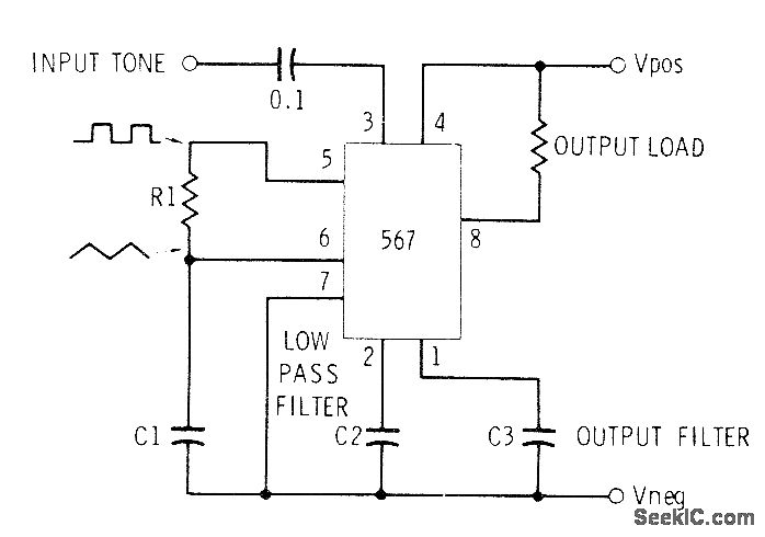
This circuit can be utilized for Touch-Tone decoding as well as for telephone line and wireless control applications using a single audio frequency. The operating center frequency is determined by components H1 and C1. The resistor R1 should be...
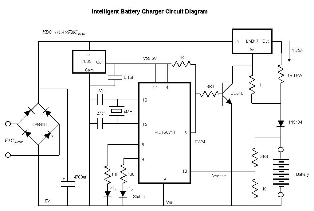
This affordable and simple-to-construct NiCd/NiMH battery charger is designed for the automatic charging of various batteries used in numerous applications. Reliable chargers are typically costly, while inexpensive chargers that come with original equipment often fail to charge cells correctly,...
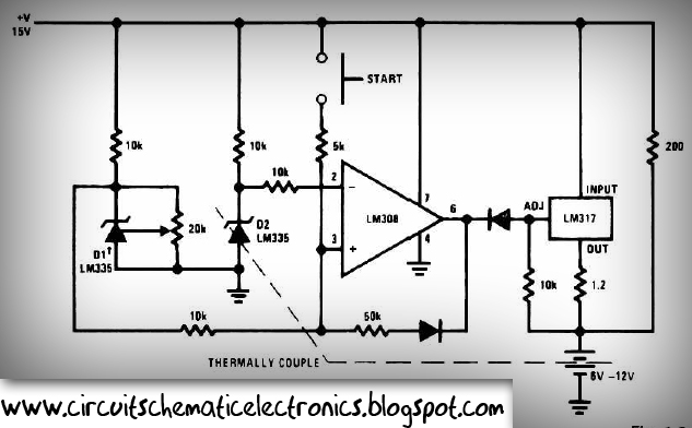
This circuit is designed for rapid battery charging. It is recommended for those who require a faster charger. The charger operates at a low temperature of 5 degrees Celsius. The input voltage is 15 volts DC, while the output...
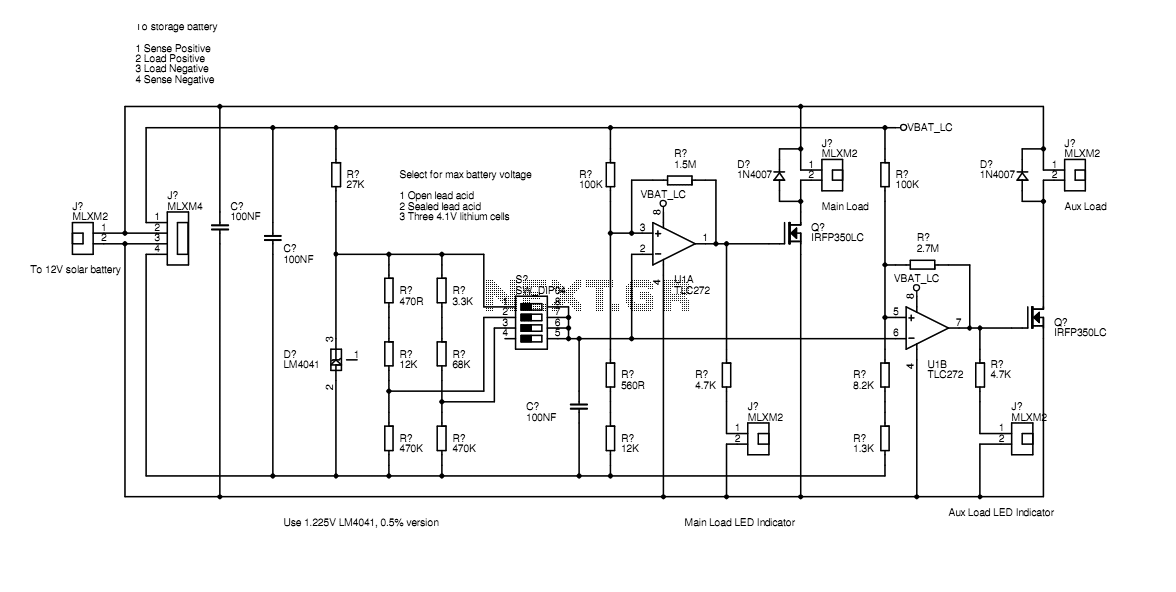
In the actual device the transistors are bolted to the aluminium case. The schematic diagram shown here represents how the circuit would be built if all components were on-board. Separate paths for load current and voltage sensing allow the...
Battery manufacturers recommend charging 12V lead-acid batteries at a charge voltage of 13.5 - 13.8V for standby, and 14.4V - 15V for cyclic use (charging and discharging). However, when using the latter option, which allows for a faster charge,...
This circuit allows appliances to remain connected to an inverter. While it does not influence weather conditions, it ensures that batteries are safely charged even during periods of generation shortfall. This device is referred to as the Grid Charger...
Warning: include(partials/cookie-banner.php): Failed to open stream: Permission denied in /var/www/html/nextgr/view-circuit.php on line 713
Warning: include(): Failed opening 'partials/cookie-banner.php' for inclusion (include_path='.:/usr/share/php') in /var/www/html/nextgr/view-circuit.php on line 713