
Voltage multipliers

The schematic for a half-wave voltage doubler is illustrated in Figure 4-44, showing similarities to half-wave voltage rectifiers. The doubler consists of two half-wave voltage rectifiers: C1 and CR1 form one half-wave rectifier, while C2 and CR2 constitute the other. The schematic of the first half-wave rectifier is indicated by dark lines in View A of Figure 4-45, with dotted lines and associated components representing the other half-wave rectifier and load resistor. During the positive alternation of the input cycle (View A), the polarity across the secondary winding of the transformer is such that the top of the secondary is negative. At this moment, CR1 is forward biased (cathode negative with respect to the anode), allowing it to operate as a closed switch and enabling current to flow along the indicated path. Consequently, C1 charges to the peak value of the input voltage, which is 200 volts, with the specified polarity. When the input cycle transitions to the negative half (View B), the polarity across the secondary of the transformer reverses, indicating that the top of the secondary winding now has a different potential.
A voltage doubler is particularly useful in applications requiring high voltage with limited current. The design effectively allows for the conversion of lower AC voltages into higher DC voltages, which can be critical in applications such as CRT displays, high-voltage power supplies for electron tubes, and other specialized electronic equipment. It is essential to ensure that the components used, such as capacitors and diodes, are rated for the high voltages generated to prevent breakdown and ensure reliable operation. Proper thermal management and circuit protection measures should also be considered, as high-voltage circuits can pose safety risks if not designed and implemented correctly.The dc output of the voltage multiplier ranges from 1000 volts to 30, 000 volts. The actual voltage depends upon the size of the CRT and its equipment application. Voltage multipliers may also be used as primary power supplies where a 177 volt-ac input is rectified to pulsating dc. This dc output voltage may be increased (through use of a voltage multiplier) to as much as 1000 volts dc. This voltage is generally used as the plate or screen grid voltage for electron tubes. If you have studied transformers, you may have learned that when voltage is stepped up, the output current decreases. This is also true of voltage multipliers. Although the measured output voltage of a voltage multiplier may be several times greater than the input voltage, once a load is connected the value of the output voltage decreases.
Also any small fluctuation of load impedance causes a large fluctuation in the output voltage of the multiplier. For this reason, voltage multipliers are used only in special applications where the load is constant and has a high impedance or where input voltage stability is not critical.
Voltage multipliers may be classified as voltage doublers, triplers, or quadruplers. The classification depends on the ratio of the output voltage to the input voltage. For example, a voltage multiplier that increases the peak input voltage twice is called a voltage doubler. Voltage multipliers increase voltages through the use of series-aiding voltage sources. This can be compared to the connection of dry cells (batteries) in series. The figures used in the explanation of voltage multipliers show a transformer input, even though for some applications a transformer is not necessary.
The input could be directly from the power source or line voltage. This, of course, does not isolate the equipment from the line and creates a potentially hazardous condition. Most military equipments use transformers to minimize this hazard. Figure 4-44 shows the schematic for a half-wave voltage doubler. Notice the similarities between this schematic and those of half-wave voltage rectifiers. In fact, the doubler shown is made up of two half-wave voltage rectifiers. C1 and CR1 make up one half-wave rectifier, and C2 and CR2 make up the other. The schematic of the first half-wave rectifier is indicated by the dark lines in view A of figure 4-45.
The dotted lines and associated components represent the other half-wave rectifier and load resistor. Notice that C1 and CR1 work exactly like a half-wave rectifier. During the positive alternation of the input cycle (view A), the polarity across the secondary winding of the transformer is as shown.
Note that the top of the secondary is negative. At this time CR1 is forward biased (cathode negative in respect to the anode). This forward bias causes CR1 to function like a closed switch and allows current to follow the path indicated by the arrows. At this time, C1 charges to the peak value of the input voltage, or 200 volts, with the polarity shown.
During the period when the input cycle is negative, as shown in view B, the polarity across the secondary of the transformer is reversed. Note specifically that the top of the secondary winding is 🔗 External reference
Related Circuits

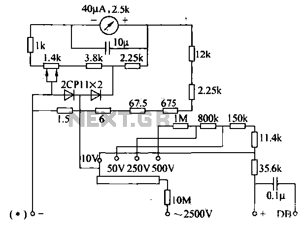
This is an application circuit for calibration known as a high voltage AC calibrator circuit. A key aspect of sine wave oscillator design is the stable control of amplitude. In this circuit, the amplitude is stabilized through servo control,...
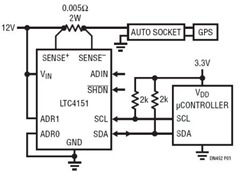
This power monitoring device accurately measures voltage and current on a positive supply rail ranging from 7V to 80V through a straightforward I2C interface, as specified in the datasheet. It is particularly suitable for automotive applications that require power...
The following circuit illustrates a low voltage power supply (PSU) for Nixie tubes utilizing a 555 Timer integrated circuit (IC). The coil used in this schematic is purchased from a store. The described circuit operates as a low voltage power...
Before designing an adjustable voltage regulator into a circuit or performing a redesign, it is necessary to calculate the values for two resistors. While this process is straightforward, sourcing the appropriate resistors may present challenges. Fortunately, a method exists...
The voltage converter can be configured to switch between AC voltage ranges using a selector switch. The measurement circuit is depicted in the accompanying figure. In this configuration, a shunt resistor is placed in parallel with the header, maintaining...
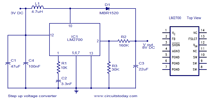
A simple DC to DC step-up voltage converter circuit schematic using the LM2700, which is a step-up switching converter. The LM2700 is a versatile step-up switching converter designed to efficiently convert a lower input voltage to a higher output voltage....