
High Voltage Low Current Supply
The High Voltage, Low Current Supply circuit is designed to provide a stable high voltage output while maintaining a low current draw. This is particularly important for applications like gas-discharge tubes and radiation detectors, where high voltage is necessary for operation, but excessive current can lead to device damage or inaccurate readings.
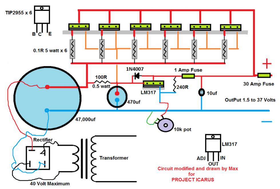
Typically, this circuit employs a step-up transformer or a voltage multiplier configuration to achieve the desired high voltage from a lower input voltage. The transformer can be designed with a primary winding connected to a standard power source, while the secondary winding is configured to produce the high voltage output. Alternatively, a voltage multiplier circuit, such as a Cockcroft-Walton multiplier, can be used to generate high voltage by stacking capacitors and diodes to incrementally increase the voltage level.
The output stage of the circuit is often equipped with a high-impedance load to ensure minimal current draw, which is essential for maintaining the integrity of sensitive components like gas-discharge tubes. Additionally, protection features such as current limiting resistors or fuses may be incorporated to prevent overcurrent conditions and ensure safe operation.
In summary, the High Voltage, Low Current Supply circuit is an essential component in various electronic applications requiring high voltage and low current, facilitating the safe and effective operation of devices like gas-discharge tubes and radiation detectors.The following circuit shows about High Voltage, Low Current Supply. Feature: Used for (biasing of gas-discharge tubes, radiation detectors, etc), .. 🔗 External reference
Related Circuits
This is a simple spanniningszoeker that is very suitable for car, for connection of alarm systems, handsfree kits, radios, etc. At rest, the yellow LED because the path of least resistance. If the probe with a positive or negative...
A DC-DC power supply schematic is required that outputs a voltage between 12.7V and 14.5VDC, with an input voltage range from 12VDC upwards. The design of a DC-DC power supply capable of outputting a regulated voltage between 12.7V and 14.5VDC...
STMicroelectronics introduces the STV0288, its latest DVB and DIRECTV QPSK digital receiver, which adds blind scan capability and DiSEqC 2.0 to the industry-leading STV0299 and provides a cost reduction path for new products. The STV0288 is a sophisticated digital receiver...
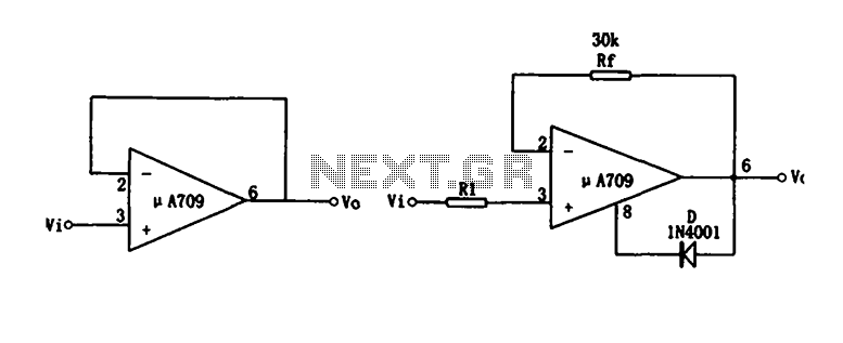
Figure (a) illustrates a voltage follower circuit, which serves as a specific instance of an in-phase amplifying circuit. The input signal originates from an integrated operational amplifier. At the conclusion of the introduction phase, the feedback resistor is set...

The circuit consists of two main sections: a charger power supply and an LED driver. The charger power supply is designed using a 3-terminal adjustable regulator (IC1) LM317, while the LED driver is based on a BD140 transistor (T2)....
The circuit diagram of the non-contact voltage detector is illustrated in Figure 1. It consists of two main components: an AC amplifier and an audio oscillator, which is based on the Schmitt trigger DD1.1 of the IC CD4093, along...
Warning: include(partials/cookie-banner.php): Failed to open stream: Permission denied in /var/www/html/nextgr/view-circuit.php on line 713
Warning: include(): Failed opening 'partials/cookie-banner.php' for inclusion (include_path='.:/usr/share/php') in /var/www/html/nextgr/view-circuit.php on line 713