
soft light dimmer circuit

The soft light dimmer circuit is an efficient solution for controlling the brightness of lighting fixtures using a combination of an Insulated Gate Bipolar Transistor (IGBT) and a timer IC. The primary component, the IGBT STGP10N50A, is selected for its ability to handle high voltages and currents, making it suitable for dimming applications. The TS555 timer is configured to operate in a mode that allows it to trigger the IGBT based on the zero crossing of the AC voltage, which minimizes electromagnetic interference and provides a smoother dimming experience.
The time constant, defined by the capacitor C5 and the resistors R14 and R15, is crucial as it determines the conduction angle of the IGBT. By adjusting these components, the dimming range can be fine-tuned to meet specific requirements. The circuit also incorporates T2 and T3, which serve as control elements to inhibit the power switch until the auxiliary supply voltage reaches a minimum threshold of 8V. This feature ensures that the IGBT gate receives a sufficient voltage level for reliable operation.
The inclusion of R5 as a current sense resistor is essential for providing protection against short circuits and over-current conditions. When the current flowing through R5 exceeds a predetermined level, the voltage across R5 will trigger the gate of the sensitive gate thyristor, causing the IGBT to turn off. This action not only protects the circuit from damage but also resets the timer, preventing further triggering until conditions are safe.
Furthermore, the current limiting feature is instrumental in managing excessive inrush currents that can occur during the initial power-up phase of the circuit. By implementing this design, the circuit achieves an automatic soft-start capability, which gradually ramps up the current, thereby reducing stress on both the IGBT and the connected load. Overall, this soft light dimmer circuit is a robust solution for controlling lighting with enhanced safety and performance.This is a design circuit for soft light dimmer. This circuit uses the IGBT STGP10N50A and the TS555 timer as main components. The timer is triggered on the zero crossing voltage pulse. The time constant determined by C5/R14+R15 that is used to determine the conduction angle. The T2 T3 inhibits the power switch until the auxiliary supply voltag e reaches 8V to guarantee that the gate of the IGBT receives correct voltage level. This is the figure of the circuit R5 is the current sense resistor, that is used for the short circuit and over-current protection. The gate of the IGBT will taken low and turn off, when the voltage across R5 reaches the sensitive gate thyristor`s gate trigger voltage.
At the same time the timer will reset. This current limiting also provides protection against excessive in-rush current and automatic soft-start. [Circuit Source: STMicroelectronics Application Note] 🔗 External reference
Related Circuits
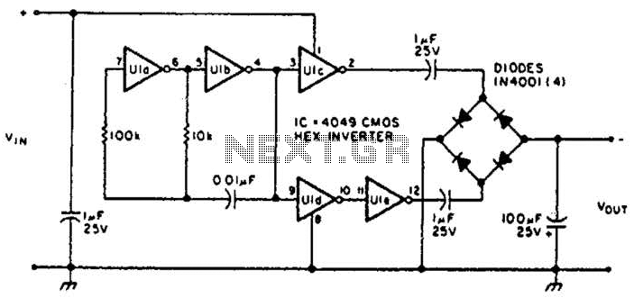
This circuit will provide a negative DC voltage that is approximately equal to the positive input voltage at no load and about 3 V less at a 10 mA load. The input voltage range is from +5 to +15...
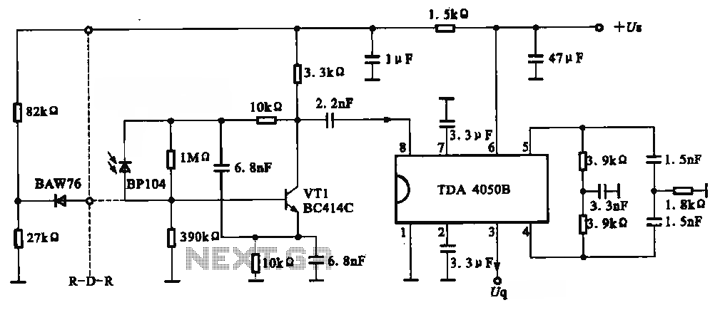
The circuit depicted is an infrared receiver circuit. It primarily consists of an infrared remote control signal switching circuit, designated as VRI, along with signal amplification, filtering, and rectifying integrated circuits, specifically the TDA4050B. The BP104 component serves as...
The circuit was designed to create ten different frequency bands that can be processed by a single graphic equalizer to produce and maintain a predetermined frequency response. The described circuit is a graphic equalizer that utilizes a multi-band approach to...
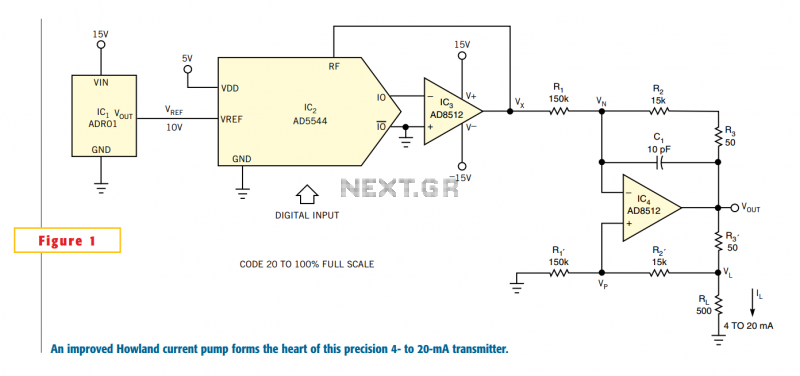
One of the key challenges in the design of 4- to 20-mA current transmitters is the voltage-to-current conversion stage. Conventional transmitters use multiple op amps and transistors to perform the conversion function. These approaches have been around for a...

The adjustable voltage monitor can be used to check whether the voltage in a circuit remains within a given range. If the DC voltage is less than the voltage at pin 5 of U1-B, then LED1 will light. If...
There are digital and analog methods that can be used to compensate for the nonlinearity of a PT100 RTD. Digital linearization can be implemented through various techniques. Compensation for the nonlinearity of a PT100 RTD (Resistance Temperature Detector) is essential...
Warning: include(partials/cookie-banner.php): Failed to open stream: Permission denied in /var/www/html/nextgr/view-circuit.php on line 713
Warning: include(): Failed opening 'partials/cookie-banner.php' for inclusion (include_path='.:/usr/share/php') in /var/www/html/nextgr/view-circuit.php on line 713