
Mixer Converter Circuits
In the context of designing frequency converter circuits, the integration of modern ICs simplifies the process significantly compared to traditional methods. The use of filters is crucial to mitigate unwanted frequency components that may arise from mixing processes. Additionally, the power supply must be appropriately designed to ensure stable operation of the IC and associated components.
In cases where a basic mixer is employed, the designer must consider various factors such as impedance matching, bandwidth, and the linearity of the mixer to achieve optimal performance. The choice of components, including transformers and capacitors, plays a vital role in determining the overall efficiency and effectiveness of the circuit.
Furthermore, understanding the conversion conductance and its implications on gain calculations allows for more informed decisions when selecting components, ensuring that the desired performance metrics are met. The noise characteristics of different tubes and their impact on the overall signal integrity must also be evaluated, especially in applications where clarity and fidelity are paramount.
The historical context provided by earlier engineering practices serves as a valuable reference for contemporary designers, highlighting the evolution of techniques and the importance of foundational knowledge in circuit design. By leveraging both modern technology and traditional principles, engineers can create robust and efficient frequency converter circuits suitable for a wide range of applications.In 2011, designing a frequency converter circuit consists in most cases of picking out an IC that has the characteristics you need from a gain and mixer spurious product standpoint, add a couple filters, and a power supply. In many cases the oscillator is part of the IC. Of course there are special cases where you have to use a basic mixer and do everything yourself, but even that is simpler than designing a tube circuit.
It really is amazing what engineers and hobbyists of yore were able to accomplish using point-to-point wiring and a slide rule. Here is a good article form the February 1941 QST magazine that discusses some of the considerations.
Maybe you have an old radio that this knowledge will apply to. THE design of an efficient mixer or converter circuit is often the one thing that prevents the amateur from building his own communications receiver. In application the amateur usually is unable to tell whether or not the stage is giving normal performance and, lacking equipment for checking gain, no attempt is made to find out if it is doing the job efficiently.
However, there are simple ways of determining whether or not a mixer or converter is operating efficiently, and it is the purpose of this discussion to explain these methods and to give some theory on the operation of converters. The general characteristics of the several mixers and converters now available are also given, with a general discussion of the performance characteristics of each.
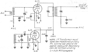
An elaborate mathematical theory of the operation of a converter or mixer1 is of no great importance for our particular problems. Roughly, a converter operates as follows: Within the tube there is developed a current at oscillator frequency which is modulated by the incoming signal to produce an intermediate frequency.
The ability of the tube to develop a current at an intermediate frequency is given by the" conversion conductance, " which by definition is the ratio of an incremental change in intermediate frequency current to the incremental change in r. f. signal voltage that produces the current. This conductance in micromhos is published for all converters, and its use to calculate stage gain is analogous to the use of mutual conductance with r.
f. amplifiers. The gain equation for a single tuned load is where Gc is the conversion conductance, Rp is the plate resistance, and RL is the tuned load resist ance. Published values of plate resistance and conversion conductance can therefore be used to calculate conversion gain.
The tabulation following gives a comparison of gain for a group of tubes now generally available. The gain figures were calculated for a tuned load impedance of 200, 000 ohms, which is equivalent to the better transformers now available. If gain was the only consideration the above would suffice for the selection of a converter tube. Tube noise is generally not a consideration when comparing converters simply because the converter is inherently a noisy device and most converters develop noise voltages of approximately the same magnitude.
The noise output of converters of the 6A8 and 6SA7 type is approximately 4 times greater than that of an r. f. amplifier like the 6SK7 or 6K7. Where the ultimate in signal-to-noise ratio is desired it is necessary to precede converters of this type with an r.
f. stage. Usually the selection of a converter is based on the characteristics of oscillator stability with regard to a. v. c. and terminal voltage fluctuation, pull-in characteristics, oscillator transconductance that determines the ease of oscillation especially at high frequencies, and other deleterious characteristics that cause loss
🔗 External reference
Related Circuits
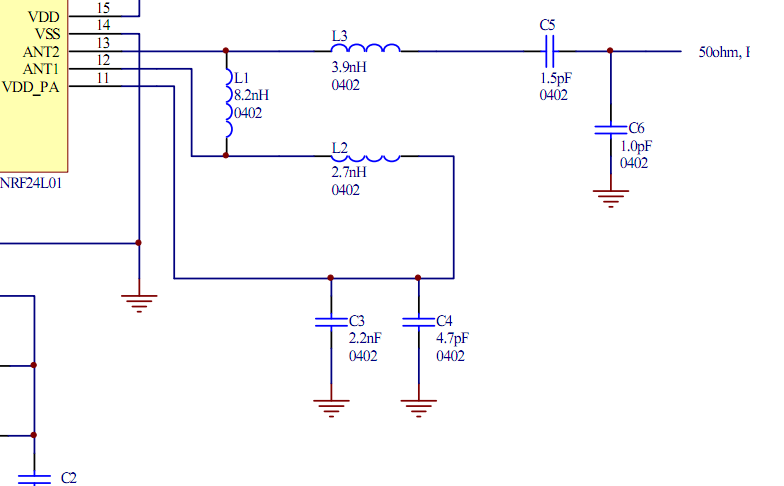
Place the transceiver and the chip antenna very close together, eliminating the need for a 50-ohm transmission line. If this is the case, can the two matching circuits be merged into one to reduce the component count? To create an...
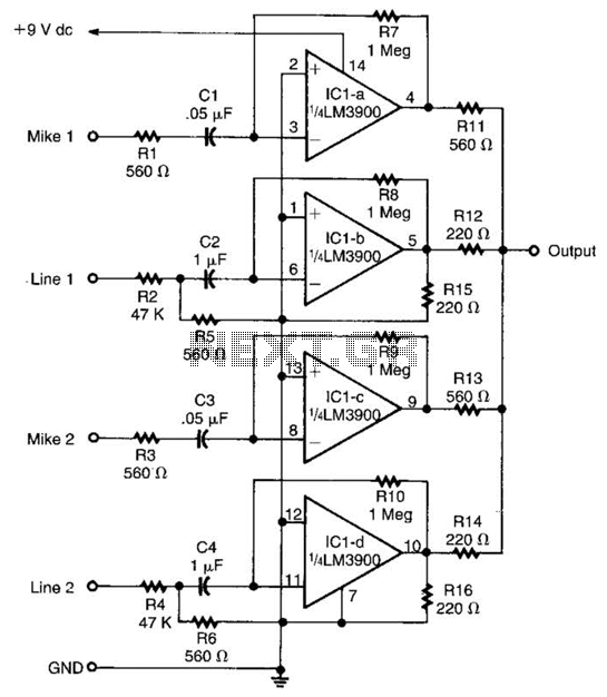
Designed around an LM3900 quad op amp, this mixer combines two line inputs and two microphone inputs, summing them at the output terminal. Resistors R7 through R10 can be adjusted to vary the gain, approximately +23 dB. The mixer circuit...
Below is the schematic diagram of an audio input module. This module is capable of producing a DC output voltage that is proportional to the amplitude of the input signal. The audio input module typically consists of several key components...
A high voltage step-up DC power supply using adjustable flyback conversion. The circuit described is a high voltage step-up DC power supply utilizing an adjustable flyback converter topology. This design is particularly effective for applications requiring a significant increase in...
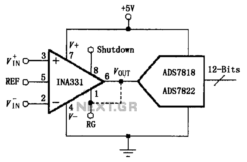
The INA331/332 is configured to directly drive a capacitive input A/D converter. Due to the low output resistance of the INA331/332, it is capable of operating at high frequencies and can directly handle capacitive loads. The output voltage from...

The pressure transmitter circuit data acquisition system utilizes the 1B31, an 18-bit A/D converter (AD1170), and an MCS-51 microcontroller. The configuration, as depicted in the accompanying diagram, features a full-scale output voltage of 10 mV from the pressure transmitter...
Warning: include(partials/cookie-banner.php): Failed to open stream: Permission denied in /var/www/html/nextgr/view-circuit.php on line 713
Warning: include(): Failed opening 'partials/cookie-banner.php' for inclusion (include_path='.:/usr/share/php') in /var/www/html/nextgr/view-circuit.php on line 713