
battet back up circuit
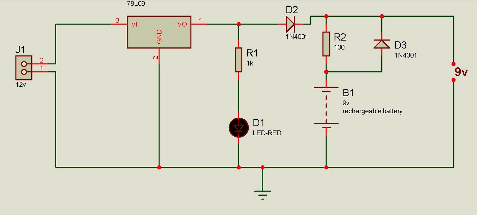
The battery backup circuit described operates as a reliable power source for critical electronic systems during power outages. The core components include the 7809 voltage regulator, which ensures a stable output of 9 volts DC necessary for the operation of the connected devices. The circuit's design incorporates a rechargeable battery, which serves as the energy storage element, ensuring that power is available when the mains supply is interrupted.
The LED indicator provides a visual confirmation of the circuit's operational status, enhancing user awareness. The forward biasing of diode D1 during normal operation allows for efficient charging of the battery while simultaneously powering the load. The calculated value of resistor R2 is crucial, as it regulates the charging current to the battery, preventing overcharging and ensuring longevity.
In the event of a power failure, the circuit seamlessly transitions to battery power. Diode D1's reverse biasing and diode D2's forward biasing facilitate this transition, allowing the circuit to draw power from the battery without interruption. This redundancy is vital for applications such as surveillance systems and alarm controls, where continuous operation is critical.
For systems requiring a different voltage, such as a 12-volt battery setup, the circuit can be modified by replacing the 7809 regulator with a 7814 regulator IC, which is designed to handle higher voltage outputs. This flexibility makes the circuit adaptable to various applications, ensuring its utility across different power requirements and battery specifications.This Battery Back-up circuit can be added to surveillance systems or control like alarms to power the circuit during Mains power failure. the battery back-up will immediatly take up the load without any delay the circuit is simple to construct.
Regulator IC 7809 volts regulated DC for powering the circuit as well as to charge the rechargeable batte ry. LED indicates the power on status, when the mains power is available, diode D1 forward biases and passes current into the battery through R2. Value of R2 is selected to give 90mA current (9/100=0. 09A)for slow charching. when the mains power failure D1 reverse baises and D2 forward biases and buck-up the circuit. the same circuit can be used in circuits having 6 volt 7. 5 Ah battery. for 12 volt battery, use 7814 regulator IC and 14 volt input 🔗 External reference
Related Circuits
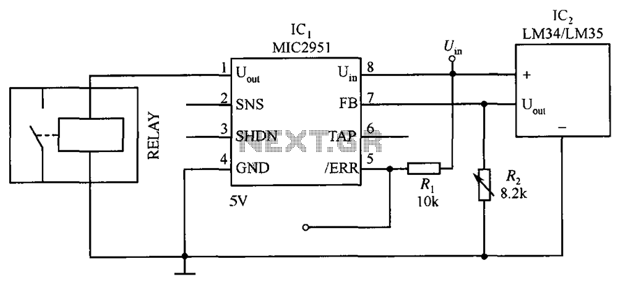
The circuit depicted in the figure utilizes a thermal protection system featuring the MIC2951 component. The temperature threshold can be adjusted by modifying resistor R2. The thermal protection circuit employing the MIC2951 is designed to monitor and regulate temperature within...
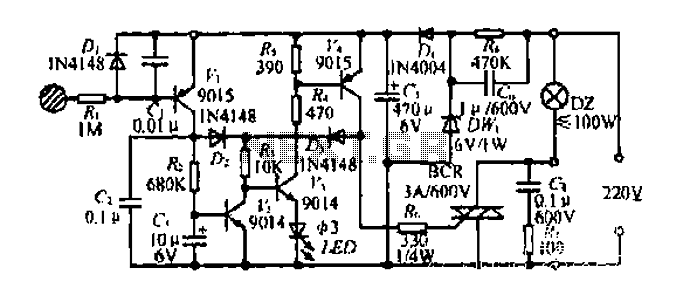
Diagram 2 depicts a shake tube circuit with a capacitance (C) and a trigger voltage rectifier filter element. The circuit includes a trigger voltage transistor amplifier (H), three pull tubes (n, U, v), and utilizes a thyristor as a...
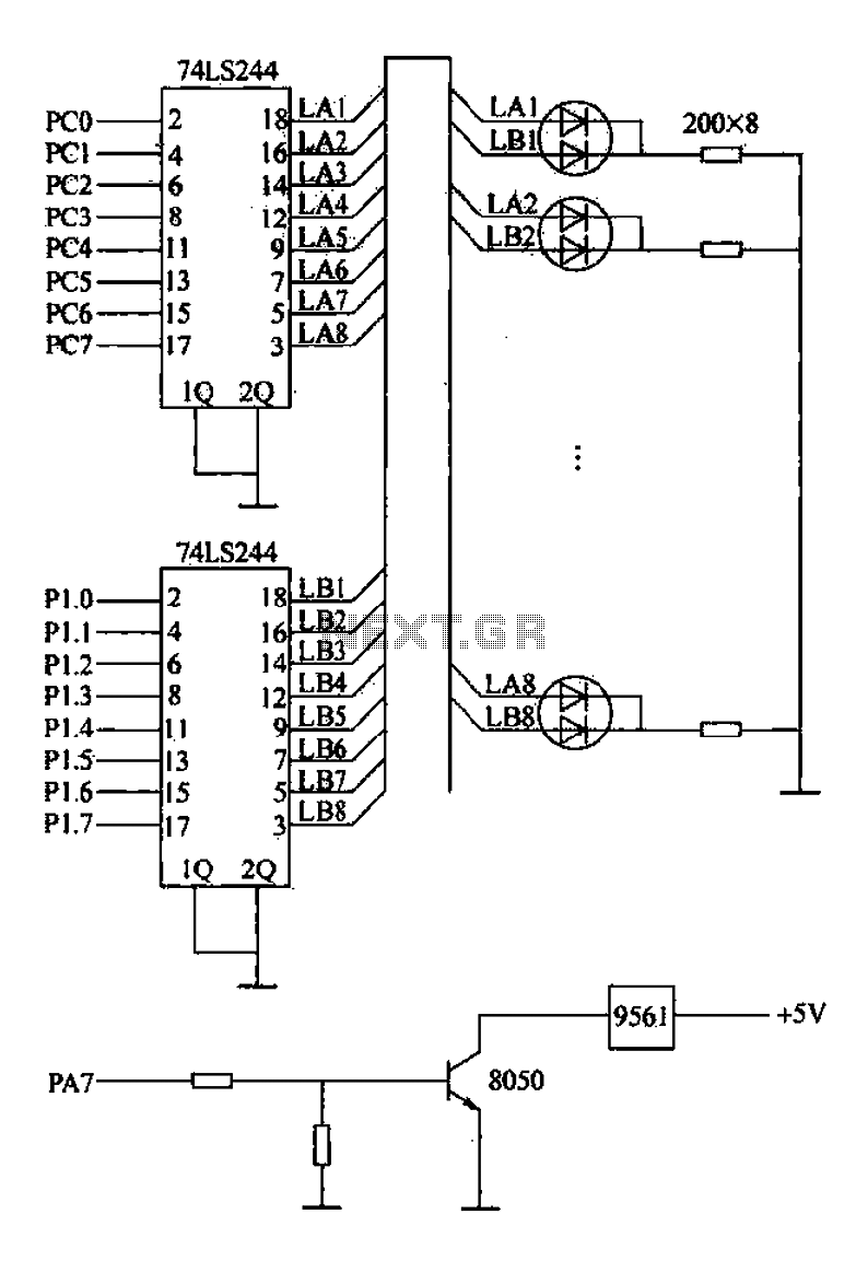
Alarm interface circuitry featuring a two-color light-emitting diode (LED) display. When LAi is at a high level and LBi is low, the green LED lights up; conversely, if LAi is low and LBi is high, the red LED lights...
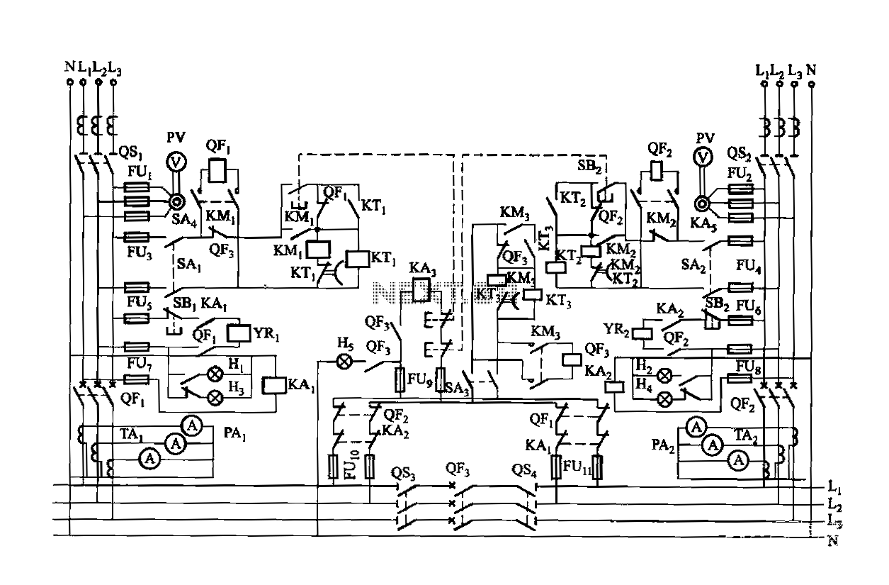
Dual power is provided for each complex, as the load is supplied through a two-way power system. In the event of a power outage, the contact switches transition from a closed position, allowing the power supply circuit to bear...
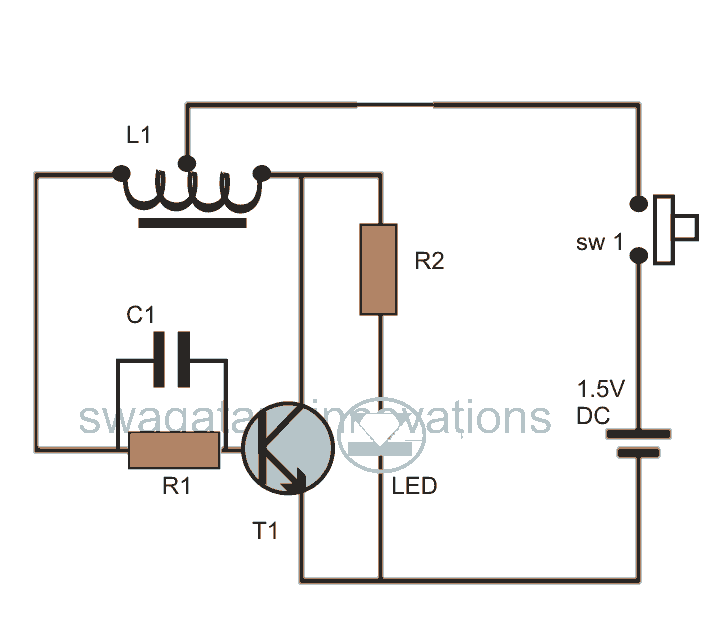
This post discusses blue and white LED drivers utilizing a joule thief circuit. Further exploration of the circuit's functionality is provided, along with simulation points. The joule thief circuit is a simple and efficient boost converter that allows for the...
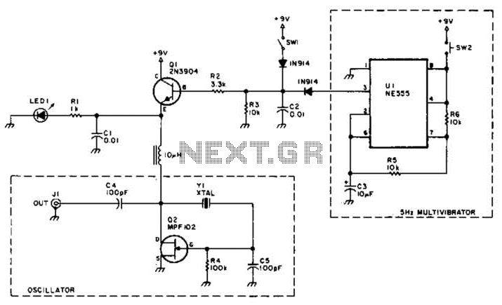
A useful marker oscillator can be constructed using an NE555 timer to generate pulses at an audio frequency. This design facilitates the detection of the signal even amidst interference. The crystal frequency can range from 1 to 30 MHz. The...
Warning: include(partials/cookie-banner.php): Failed to open stream: Permission denied in /var/www/html/nextgr/view-circuit.php on line 713
Warning: include(): Failed opening 'partials/cookie-banner.php' for inclusion (include_path='.:/usr/share/php') in /var/www/html/nextgr/view-circuit.php on line 713