
Baxendall tone control circuit

The tone control circuit based on the Baxendall design utilizes a combination of passive and active components to achieve effective audio signal manipulation. The circuit begins with the input stage, where the BC109 transistor (Q1) operates as an emitter follower. This configuration is advantageous as it offers a high input impedance, allowing it to interface seamlessly with various audio sources without loading them down. The emitter follower arrangement ensures that the input signal is buffered, resulting in minimal distortion and maintaining the integrity of the audio signal.
The passive Baxendall tone control network is integrated following the input stage, utilizing capacitors and resistors to shape the frequency response. The use of capacitor C1 serves to couple the output from the emitter follower to the tone control circuitry, blocking any DC offset while allowing AC audio signals to pass. The independent adjustment of bass and treble through potentiometers R7 and R10 provides users with flexibility in shaping the sound to their preference. The design allows for a substantial boost or cut in both frequency ranges, enhancing the listening experience across various audio playback scenarios.
The final output stage, formed by transistor Q2 and its associated resistors (R11, R12, and R13), amplifies the processed audio signal. This stage is crucial for increasing the signal level to a usable output for subsequent amplification stages or speakers. The overall voltage gain of three ensures that the audio signal is sufficiently amplified while preserving the tonal adjustments made in the earlier stages.
The circuit's design is compact and efficient, making it suitable for integration into various audio applications, including home audio systems, musical instruments, and other electronic devices requiring tone control. Proper layout and component selection will further enhance the performance and reliability of the circuit, ensuring high-quality audio output.This simple tone control circuit is designed based on the famous Baxendall tone control circuitry. The circuit given here can give a maximum cut or boost of around 12 dB at 10 KHz (treble) and 50Hz (bass). Also, both bass and treble can be independently adjusted. Transistor Q1 (BC109) and its associated components (R1, R2 and R3) form an emitter f ollower which is the input stage. The voltage gain of this input stage is around 1 and it has an input impedance of around 225K ohms. The output of the input stage is coupled to the passive Baxendall circuitry using the capacitor C1. POT R7 can be used to adjust the bass and POT R10 can be used to adjust the treble. Transistor Q2 and associated components (R11, R12 and R13) forms the final output stage which gives an overall voltage gain of three to the system. 🔗 External reference
Related Circuits
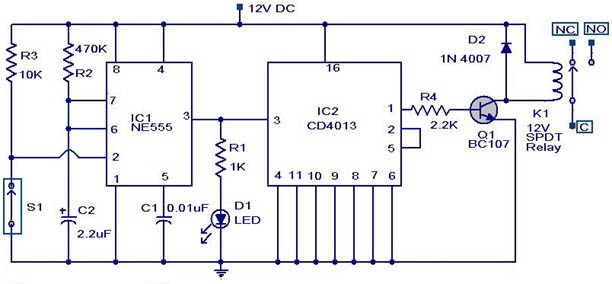
This weblog discusses electronic circuit schematics, PCB design, DIY kits, and electronic project diagrams. The circuit diagram presented is for a magnetic proximity switch, which has numerous applications across various fields. The circuit utilizes a magnetic reed switch (S1)...

The RS-232 system connection is faster and easier, but the distance is limited. Therefore, this project involves using an RS-485 system with an RS-232 to RS-485 converter. The RS-232 to RS-485 converter project aims to extend the communication range and...
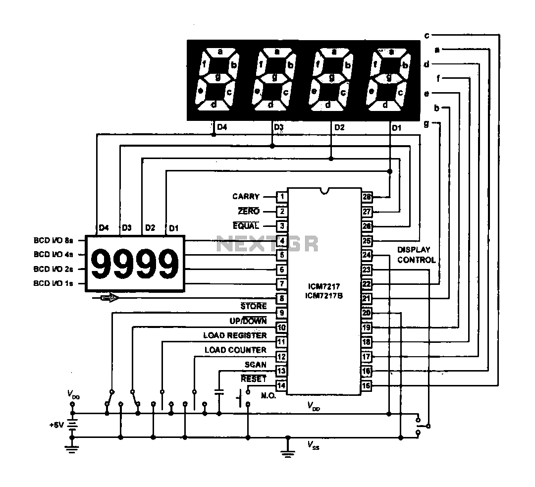
The circuit drives the light-emitting diode in a digital display configuration. The count signal is fed into the ICM7217 chip, which processes the count and subsequently drives the digital display board. The connection between the thumbwheel switches is illustrated...

This sound-activated switch allows for sound control, which can be beneficial not only for robotic applications but also for home automation. The sound-activated switch operates by detecting specific sound frequencies or patterns, enabling the user to control various devices or...
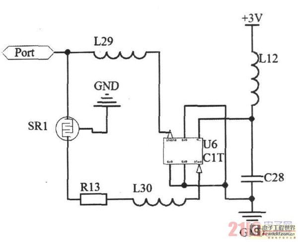
Due to the small size, high precision, and sensitivity of surface acoustic wave (SAW) sensors, along with their cost-effectiveness, a SAW gas sensor has been developed. This sensor comprises a surface acoustic wave device, a sensitive membrane, and the...
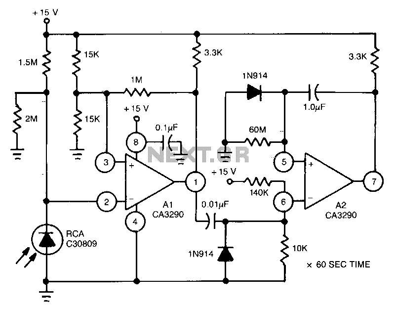
This circuit utilizes the CA3290 BiMOS dual voltage comparator to detect variations in the current of a light-emitting diode (LED). The output from the comparator triggers A2, a one-shot timer. If the light source to the photodiode is disrupted,...