
BayComm packet modem
This circuit description outlines the specifications and assembly instructions for a modem circuit utilizing a 9-pin D-type connector and a 5-pin DIN socket. The PCB design incorporates specific hole diameters for both connectors, ensuring compatibility and secure mounting. The 9-pin D-type connector features outer mounting holes with a diameter of 3mm and pin holes measuring 1.2mm, while the 5-pin DIN socket also follows the same pin hole specifications. The remaining holes on the PCB are standardized to a diameter of 0.9mm, allowing for various components to be securely attached.
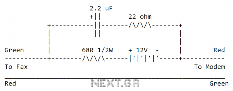
The inclusion of a 22K resistor near the 5-pin DIN socket is conditional, dependent on the transceiver's Push-To-Talk (PTT) switch configuration. This resistor is necessary when the PTT switch operates through a DC short on the microphone lead, a common setup in handheld radios.
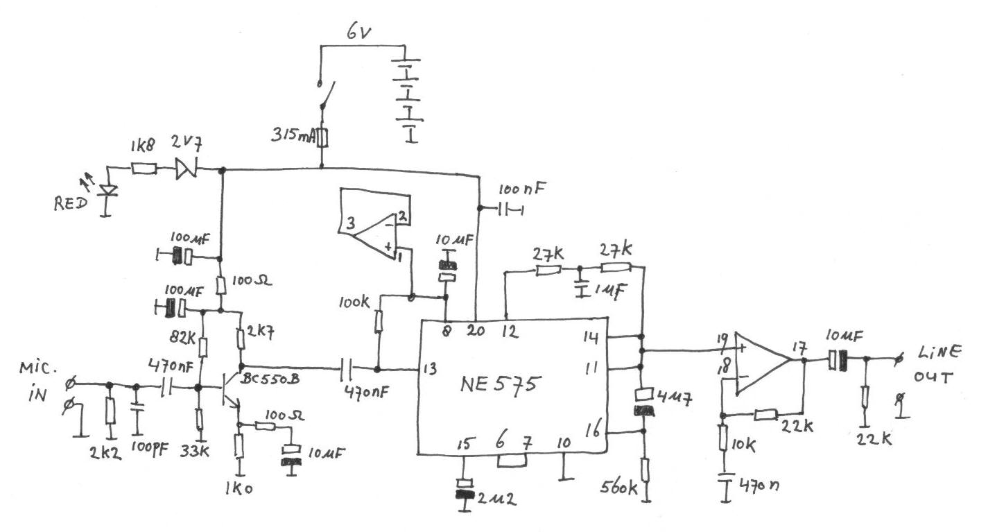
For alignment purposes, the circuit requires the use of an oscilloscope. By connecting the oscilloscope to the receiver and opening the squelch on an unused channel, the waveform at pin 6 of the 74HC04 can be monitored. The adjustment of a 47K potentiometer is crucial to ensure that the noise waveform is centered on the oscilloscope display, indicating proper modulation levels. If an oscilloscope is unavailable, an alternative method involves adjusting the potentiometer to achieve a DC voltage of 2.5V at pin 6.
Further details regarding software setup are provided in the accompanying ZIP package, which includes all necessary files for installation and configuration. The PCB layout and component overlay are accessible in the DOWNLOAD section of the website, facilitating easy reference during assembly. For those interested in a pre-manufactured PCB, options are available on the KITS page, with future availability of a ready-made PCB anticipated. Although the TCM3105 component is deemed obsolete, it remains obtainable through specific suppliers, ensuring that the circuit can be constructed effectively.Be sure to use the correct 9-pin `D` type connector so the pins fit in the board. The two outer holes for mounting the 9-pin `D` type connector should be 3mm Dia. and the holes for the pins are 1. 2mm Dia. The PCB is also tailored for a PCB mounting 5-pin DIN socket. These holes should also be 1. 2mm Dia. All other holes on the PCB are 0. 9mm Dia. The 22K resistor close to the 5-pin DIN socket is only fitted when your transciever PTT switch is by means of a DC short on the MIC lead (most hand-held radio`s). Here is my finished modem. To align the modem, using an oscilloscope, connect it to the receiver and open the squelch on an unused channel and watch the waveform on pin 6 of the 74HC04.
Adjust the 47K pot so that the noise is centered on the screen and not all at the top or bottom of the screen - i. e. the noise should be just as much positive 5v as it is 0v. If you do not have an oscilloscope then adjust the 47K for a DC voltage of 2. 5v on pin 6 of the 74HC04. Full instructions for setting up the softw1are are given in the softw1are ZIP package. The PCB foil, component overlay and Baycom softw1are are given in the DOWNLOAD section of my homepages.
If you want a PCB ready made then just look at my KITS page. I hope to have a ready made PCB available soon. The TCM3105 is supposed to be obsolete but you can still buy it from N R Bardwell, see my Component suppliers page. 🔗 External reference
Related Circuits
Overview: The DS8500 is a single-chip modem with Highway Addressable Remote Transducer (HART®) capabilities and meets the HART physical layer requirements. The device integrates the modulation and demodulation of the 1200Hz/2200Hz FSK signal. The DS8500 modem is designed to facilitate...
This application note details the operation and features of the FAN7601, a BCDMOS programmable frequency current mode PWM controller designed for offline adapter applications and auxiliary power supplies. To minimize power loss during light and no-load conditions, the FAN7601...
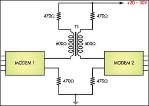
Connecting two PCs via modems using a twisted pair cable may not yield any results because the modems are designed to operate over a phone line. The scenario described involves the attempt to establish a connection between two personal computers...
A toroidal transformer (2x12V 15VA) is utilized due to its significantly lower energy losses compared to an E-I core transformer, which was employed in the original mains adapter. The toroidal transformer is a type of transformer that features a doughnut-shaped...
The circuit can be easily built to a small plastic box with telephone connectors in both ends. The circuit takes about 10-20 mA current, so if the circuit is not in use all the time it is best to...
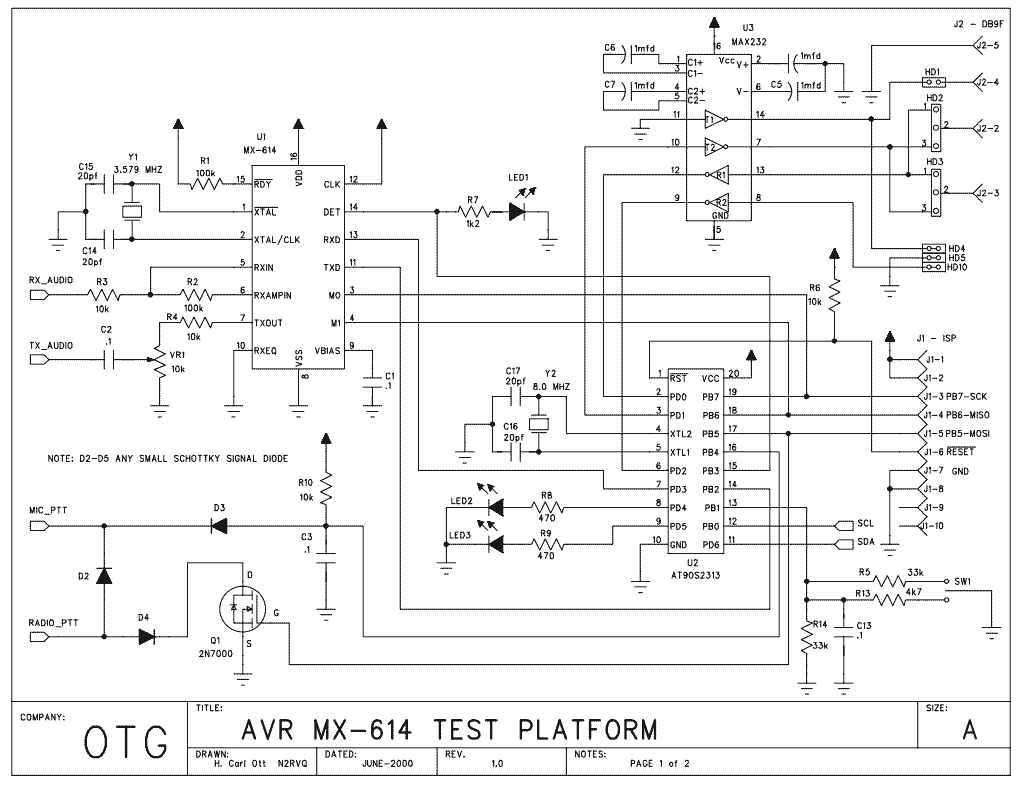
Here is some experimental hardware and software to transmit and receive AX.25 packets. It is essentially a PIC-E clone designed around a Atmel AT90S2313 with a few extra bells and whistles. I had picked up a couple of MXCOM...