
BC548 Heat Sensor Diagram Circuit
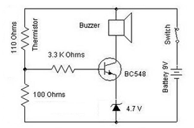
The heat sensor circuit operates on the principle of temperature-dependent resistance changes in the thermistor. The NTC thermistor is critical in this design, as it allows for the detection of temperature variations. As the ambient temperature rises, the decrease in thermistor resistance leads to an increase in current through the potential divider, resulting in a higher voltage at the junction of the thermistor and resistor. This voltage is crucial for controlling the transistor.
The BC548 NPN transistor serves as a switching element in the circuit. The base resistor of 3.3 kΩ limits the current into the base of the transistor, ensuring that it operates within safe parameters. The use of a Zener diode for the emitter stabilizes the voltage, providing a reliable reference for the base-emitter junction. When the input voltage at the base exceeds 4.7 volts, the transistor enters saturation, allowing current to flow from the collector to the emitter, thus activating the buzzer.
This circuit is versatile and can be adapted for various applications, such as temperature alarms, automatic fans, or other devices that require temperature monitoring and control. The design is straightforward and can be implemented with minimal components, making it suitable for educational projects or practical applications in temperature-sensitive environments.Heat sensor circuit can be used to control any device using heat sensor. In this circuit a thermistor and a resistance is connected in series. This arrangement makes a potential divider circuit. Here the thermistor is Negative Temperature Coefficient type. So when the room temperature is increased its resistance decreases simultaneously and more c urrent flows through the resistor and the thermistor. We find more voltage at the junction of the resistor and the thermistor. Our thermistor resistance value is 110 ohms. Suppose the resistance value becomes 90 ohms after heating the 110 ohms thermistor. Then the voltage across one resistor of the voltage divider circuit equals the ratio of that resistor`s value and the sum of resistances of the voltage across the series combination. This is the concept of voltage divider. The final output voltage of the voltage divider circuit is now applied to the npn transistor (BC548) through the base resistor (3.
3K ohms). Here the emitter resistor is replaced with a zener diode. Emitter voltage is maintained at 4. 7volt with the help of zener diode. This voltage is used to compare voltage. Transistor conducts when base voltage is greater than the emitter voltage. Transistor conducts if it gets more than 4. 7volt of base voltage. Then the circuit is completed through buzzer and it gives sound. 🔗 External reference
Related Circuits
A high-input-resistance op-amp, a bridge rectifier, a microammeter, and a few other discrete components are all that are required to realise this versatile circuit. This circuit can be used for measurement of dc, ac rms, ac peak, or ac...
This circuit is appropriate for any scenario where over-current protection is necessary. An example from the model train hobbyist community illustrates its importance. Experienced model train enthusiasts understand that locating the source of a short circuit can be quite...
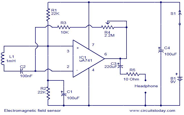
This is a very simple circuit that can be used to sense electromagnetic radiations. The circuit can even detect hidden wires. A 1mH inductor is used for sensing the electric field. The electric field will induce a small voltage...
2 versions of the equalization circuit, the first having 6 dB less insertion loss than the other. However, some may not be able to find a 0.68 microfarad capacitor. The second version uses a more common 0.22 microfarad capacitor....

A basic LED driver circuit consists of a 5-volt power source, a 2 kΩ potentiometer, and an LED. The LED is forward biased, with the manufacturer specifying a maximum current rating of 20 mA at a diode voltage drop...
This circuit is designed for children's entertainment and can be installed on bicycles, battery-powered cars, motorcycles, as well as models and various games and toys. When switch SW1 is positioned as indicated in the circuit diagram, it generates the...