
Voltmeter circuit
The described circuit is a versatile measurement device capable of accurately gauging various types of voltage signals, including direct current (DC), root mean square (RMS) alternating current (AC), peak AC, and peak-to-peak AC voltages. At its core, the circuit employs a high-input-resistance operational amplifier (op-amp) to ensure minimal loading on the measurement source, thus preserving the integrity of the voltage being measured.
The circuit topology includes a bridge rectifier, which converts AC signals into a usable DC format for the microammeter, allowing for direct reading of the measured voltage. The microammeter serves as the output display, providing a visual indication of the voltage level being measured. The configuration of the op-amp in a voltage-to-current converter mode is crucial for translating the input voltage to a corresponding current that drives the microammeter.
The user can select the measurement type by adjusting a function switch, which alters the circuit's configuration to accommodate different voltage types. Each position of the switch is calibrated for a specific measurement range, allowing for full-scale deflection of 5V for each measurement type. The equations provided for calculating the resistor values (RI) are essential for tailoring the circuit to specific applications, ensuring accurate readings based on the voltage type and desired full-scale deflection.
In the case of DC measurements, the resistor value is determined directly from the full-scale DC voltage and the full-scale current rating of the microammeter (IFS). For AC measurements, the calculations take into consideration the RMS value for sine waves, with specific coefficients applied to account for the nature of the AC signal. This versatility in measurement capabilities, coupled with straightforward calibration procedures, makes the circuit an invaluable tool for electrical engineers and technicians engaged in voltage measurement tasks.
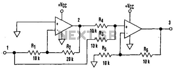
It is important to note that the performance of the circuit remains unaffected by the resistance of the microammeter or any voltage drops across the diodes in the bridge rectifier, ensuring accurate current readings regardless of these factors. This design consideration further enhances the reliability and precision of the measurement circuit in practical applications.A high-input-resistance op-amp, a bridge rectifier, a microammeter, and a few other discrete components are all that are required to realise this versatile circuit. This circuit can be used for measurement of dc, ac rms, ac peak, or ac peak-to-peak voltage by simply changing the value of the resistor connected between the inverting input terminal of the op-amp and ground.
The voltage to be measured is connected to non-inverting input of the op-amp. The full-scale deflection of the universal high-input-resistance voltmeter circuit shown in the figure depends on the function switch position as follows: (a) 5V dc on position 1 (b) 5V ac rms in position 2 (c) 5V peak ac in position 3 (d) 5V ac peak-to-peak in position 4 The circuit is basically a voltage-to-current converter. The design procedure is as follows: Calculate RI according to the application from one of the following equations: (a) dc voltmeter: RIA = full-scale EDC/IFS (b) rms ac voltmeter (sine wave only): RIB = 0.9 full-scale ERMS/ IFS (c) Peak reading voltmeter (sine wave only): RIC = 0.636 full-scale EPK/IFS (d) Peak-to-peak ac voltmeter (sine wave only): RID = 0.318 full-scale EPK-TO-PK / IFS The term IFS in the above equations refers to meter?s full-scale deflection current rating in amperes.
It must be noted that neither meter resistance nor diode voltage drops affects meter current. 🔗 External reference
Related Circuits
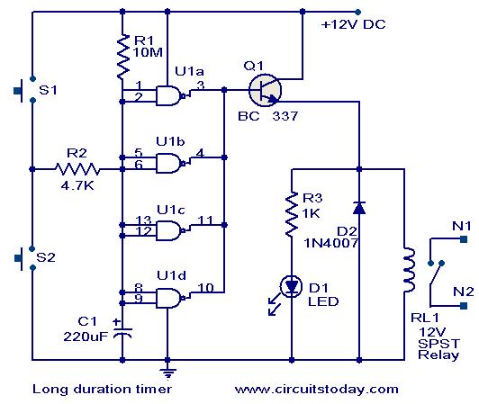
This timer circuit is designed to turn off a specific device after approximately 35 minutes. It can be utilized to switch off appliances such as radios, TVs, fans, and pumps after a predetermined duration of 35 minutes, contributing to...
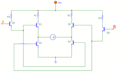
The transistors Q1, Q2, Q3, and Q4 form a bridge circuit. These are typically power transistors designed to handle high current. Transistors Q5 and Q6 drive the bridge. When input A is set high and input B is set...
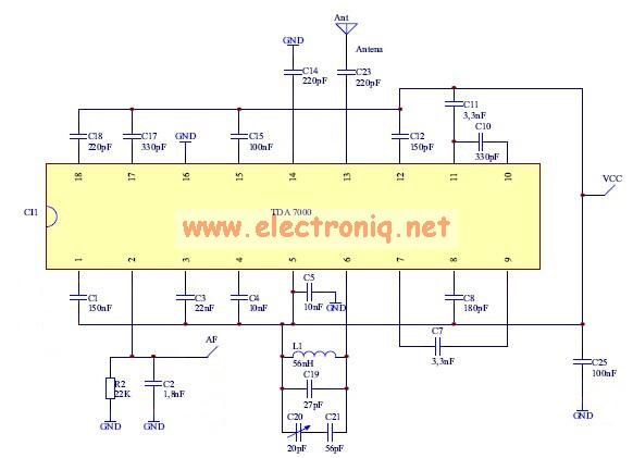
The TDA7000 features a Frequency-Locked-Loop (FLL) system with an intermediate frequency of 70 kHz, and selectivity is achieved through active RC filters. The only calibration required is for the resonant circuit associated with the oscillator, which is necessary for...
This circuit regulates a DC power output and has a wide range of applications. It can be utilized to control the speed of a motor, a pump, a toy train, or the brightness of an LED or lamp. Essentially,...
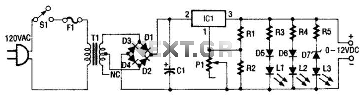
This 0- to 12-Vdc variable power supply utilizes an integrated circuit (IC) voltage regulator along with a robust transformer to deliver a dependable DC power output. The schematic illustrates that transformer T1 has a primary voltage of 120 V...
It is well understood that utilizing single-supply operational amplifiers (op amps) can present challenges when implementing simple functions in a bipolar signal environment. Often, this necessitates the use of additional op amps and other electronic components. Considering this, it...
Warning: include(partials/cookie-banner.php): Failed to open stream: Permission denied in /var/www/html/nextgr/view-circuit.php on line 713
Warning: include(): Failed opening 'partials/cookie-banner.php' for inclusion (include_path='.:/usr/share/php') in /var/www/html/nextgr/view-circuit.php on line 713