
Beacon Transceiver Project
There are numerous VFO kits around, many of which are suitable for operation with a 1650kHz IF single-conversion transceiver. Check at the bottom of this page for the technique used to connect the VFO to the transceiver. In their original application these radios invariably offer only USB operation. Typically LSB operation is obtained by the simple expedient of operating the VFO below the required band, rather than above it. The image rejection on 160m may however be poor using this technique. Otherwise image rejection should be good up to 15MHz or so. If operating with the VFO below the required band is not appropriate to your application, you will need to find a way to add an extra crystal filter, or a second BFO crystal.
Whichever VFO you choose, make sure that the off-frequency spurs generated are low. Generally the spurs won`t affect the transmitted signal, but a spur 40dB down may cause a strong short wave broadcast station to be received when you least expect it, in the middle of a ham band. Phase noise on the VFO will have a direct impact on the sensitivity of the receiver, and will also affect signal quality on transmit and receive.
DDS VFOs inherently have low phase noise. The Si570 type also have acceptably low phase noise for HF operation. You can connect the DDS VFO (or any other VFO) to as many channels as you like, and leave the others crystal controlled. For each channel you connect, you will need a 10nF ceramic capacitor, and of course remove the crystal (if fitted).
The connecting scheme is the same for all models of Codan crystal controlled radios, and may be similar for others. The following information is based on the 7727. At the left you can see the channel switch. It connects each crystal in turn by forward biassing a diode, e. g. D36, via a resistor, e. g. R47. The other side of each crystal goes to an individual trimmer and set of fixed capacitors. On each channel you wish to operate the VFO, remove the crystal, e. g. Z2, and fit one lead of a 10nF 50V ceramic capacitor in the crystal hole corresponding to the end by the diode (NOT the end by the trimmer).
Cut the other lead short, and connect all the short ends of these capacitors together with a length of tinned wire. Drive these capacitors with the output of the VFO via a series 100 Ohm resistor. The level will not matter - anywhere from 50mV to 1V RMS - this circuit is self-levelling! If you look at the oscillator circuit, V11 is the actual oscillator (grounded emitter Colpitts circuit), while V12 is a buffer and V13 is an AGC amplifier.
(V14 drives the mixer). The AGC developed by D45 and V13 is fed back via R55 to change the gain of the oscillator V11. When you drive the oscillator transistor with a VFO via 100 Ohm, you are actually driving the buffer V12, and the collector of V11, which can no longer oscillate. Instead, the AGC bias operates V11 as a variable resistor, forming an attenuator with your 100 Ohm resistor, and controlling the drive to V12.
Any channels you leave intact will operate normally using crystal control. Essentially the same circuit is used in the 6801, 6924 Mk. 2 and 8121 radios. Just look for the crystal connection points and fit the capacitors accordingly. The Clarifier will still work in models where it operates on the BFO crystal. 🔗 External reference
Related Circuits
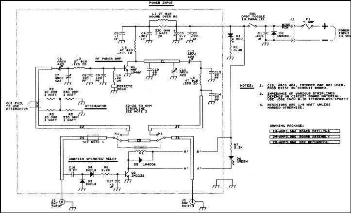
This article discusses a 2-meter amplifier capable of delivering an output of 25-30 watts. Over 35 units have been acquired at a cost of less than $50 each in bulk. Photo A displays the final version of the circuit...

The LTC3113 fixed frequency buck-boost DC-DC converter can be utilized to design various power supply circuits that operate with input voltages that are above, below, or equal to the output voltage. The topology integrated into the IC ensures low...
This is a simple microphone preamplifier circuit designed for use between a microphone and a stereo amplifier. This circuit is compatible with standard home stereo amplifier line, CD, aux, and tape inputs. It can accept both dynamic and electret...
The HC-06 module is a slave mode serial Bluetooth data link manufactured by CSR. In this project, a mobile phone communicates with the AT89C2051 microcontroller via the HC-06 module. The complexity of the communication has been encapsulated within a...
To manufacture large quantities of products, a manufacturing system or process is essential. This process can be categorized as either open-loop or closed-loop. In an open-loop system, variables are controlled manually, whereas in a closed-loop system, they are controlled...
The AVR Basic Infrared Transmitter is a companion project to the Basic Infrared Receiver. This project is termed "basic" because it can be constructed using only 10 discrete components along with a standard AVR microcontroller. Together, these two projects...