
Project [E-20] Infrared Data Transmitter
The operating frequency is crucial as it directly influences the bitrate. The AVR program is designed for a 4.00 MHz clock. If a different bitrate is required, modifications can be made to the program for other clock rates. It is important to consider the current draw of the infrared emitter, particularly when utilizing "high-output" or "high-brightness" diodes, which may require up to 100 mA for peak emission, significantly exceeding the 20 mA to 30 mA that typical controllers are rated for.
Not all infrared emitters are identical; each has a unique wavelength (measured in nanometers), which corresponds to a color if visible. Prior to selecting an emitter, it is essential to ensure compatibility with the receiver's "infrared passband," which filters out wavelengths outside its specified range. For example, a receiver may have a passband of 940 nm ± 50 nm (ranging from 890 nm to 990 nm), and an emitter rated at 915 nm would be suitable, though not ideal. Caution is advised when purchasing unknown diodes, as some can have wavelengths as long as 1550 nm.
The system's simplicity allows for the construction of a robust transmitter from a wide variety of electronic components. The software-generated carrier eliminates the need for signal mixing, transferring most of the engineering complexity to the software. For details on the RC5 remote control protocol and its implementation in this device, refer to the Basic Infrared Receiver Software Design section. The application of the RC5 protocol necessitates the transmission of data.
This circuit design utilizes a basic AVR microcontroller as the core processing unit, interfacing with an infrared LED for transmission. The microcontroller is configured to generate a modulated signal at the appropriate frequency, which is then sent to the infrared emitter. The choice of components includes resistors to limit current to the LED, capacitors for signal stabilization, and possibly a transistor for switching the emitter on and off, depending on the design requirements.
The schematic would typically illustrate the connections between the microcontroller's output pins and the infrared emitter, along with power supply connections. It is also advisable to include bypass capacitors near the power pins of the microcontroller to ensure stable operation.
In summary, the AVR Basic Infrared Transmitter is a straightforward yet effective solution for remote control applications, leveraging the simplicity of AVR microcontrollers and a minimal number of components to achieve reliable infrared communication.The AVR Basic Infrared Transmitter is a sister project for the Basic Infrared Reciever. The emphasis here is on "basic" because the simplest version can be built using only 10 discrete components and a typical AVR microcontroller. Taken together, these two projects will allow your projects to be remotely operated for distances averaging as far as
10 meters. ALL INFORMATION WITHIN THIS DOCUMENT IS PROVIDED "AS IS" AND WITHOUT ANY EXPRESS OR IMPLIED WARRANTIES, INCLUDING, WITHOUT LIMITATION, THE IMPLIED WARRANTIES OF MERCHANTIBILITY AND FITNESS FOR A PARTICULAR PURPOSE. I DO NOT GUARANTEE ANY INFORMATION IN THIS DOCUMENT IS ACCURATE, AND IT SHOULD BE USED FOR ABSTRACT EDUCATIONAL PURPOSES ONLY.
THIS SOFTWARE AND DOCUMENTATION IS FREE OF CHARGE. COPYRIGHT (C) 2005 BY BRADY MAYES. ALL RIGHTS RESERVED. REDISTRIBUTION AND USE IN SOURCE AND BINARY FORMS, WITH OR WITHOUT MODIFICATION, ARE PERMITTED PROVIDED THAT THE FOLLOWING CONDITIONS ARE MET: 2. REDISTRIBUTIONS IN BINARY FORM MUST REPRODUCE THE ABOVE COPYRIGHT NOTICE, THIS LIST OF CONDITIONS AND THE FOLLOWING DISCLAIMER IN THE DOCUMENTATION AND/OR OTHER MATERIALS PROVIDED WITH THE DISTRIBUTION.
3. ALL ADVERTISING MATERIALS MENTIONING FEATURES OR USE OF THIS SOFTWARE MUST DISPLAY THE FOLLOWING ACKNOWLEDGEMENT: THIS PRODUCT INCLUDES SOFTWARE DEVELOPED BY B. MAYES AND ITS CONTRIBUTORS. THIS SOFTWARE IS PROVIDED BY B. MAYES AND CONTRIBUTORS ``AS IS`` AND ANY EXPRESS OR IMPLIED WARRANTIES, INCLUDING, BUT NOT LIMITED TO, THE IMPLIED WARRANTIES OF MERCHANTABILITY AND FITNESS FOR A PARTICULAR PURPOSE ARE DISCLAIMED.
IN NO EVENT SHALL B. MAYES OR CONTRIBUTORS BE LIABLE FOR ANY DIRECT, INDIRECT, INCIDENTAL, SPECIAL, EXEMPLARY, OR CONSEQUENTIAL DAMAGES (INCLUDING, BUT NOT LIMITED TO, PROCUREMENT OF SUBSTITUTE GOODS OR SERVICES; LOSS OF USE, DATA, OR PROFITS; OR BUSINESS INTERRUPTION) HOWEVER CAUSED AND ON ANY THEORY OF LIABILITY, WHETHER IN CONTRACT, STRICT LIABILITY, OR TORT (INCLUDING NEGLIGENCE OR OTHERWISE) ARISING IN ANY WAY OUT OF THE USE OF THIS SOFTWARE, EVEN IF ADVISED OF THE POSSIBILITY OF SUCH DAMAGE. THIS FILE IS DISTRIBUTED IN THE HOPE THAT IT WILL BE USEFUL, BUT WITHOUT ANY WARRANTY; WITHOUT EVEN THE IMPLIED WARRANTY OF MERCHANTABILITY OR FITNESS FOR A PARTICULAR PURPOSE.
The operating frequency is critical since it directly controls the bitrate. The AVR program on this page was designed for a 4. 00MHz clock. If you need a different bitrate, please view the software section below for details on how to rewrite the program for other clock rates. Be aware of how much current will be drawn by your infrared emitter, especially when using "high-output" or "high-brightness" diodes.
Often, these diodes require 100mA for peak emission, which is much greater than the 20mA or 30mA garden-variety controllers are designed to take. Not all infrared emitters are created equal. Like visible LEDs, each has a distinct wavelength (measured in nanometers), which would corespond to a color if we could view it.
Before choosing an emitter, know that your receiver will have an "infrared passband" that will filter out any wavelengths that don`t fall within that range. My receiver had an advertised passband of 940nm +/- 50nm-or 890nm to 990nm. The emitters I purchased were rated 915nm. Not an ideal match, but well within the limits. On the market, I`ve seen diodes with wavelengths as long as 1550nm, so beware if purchasing an unknown diode.
Thanks to the software-generated carrier, no signal mixing is required and the engineering burden is mostly shifted onto the software aspect. In general the system`s simplicity makes it possible to build a highly robust transmitter out of nearly any grade of electronic component.
For a description of the RC5 remote control protocol, and the a description of the protocol I used in this device, view the Basic Infrared Receiver Software Design section. Since we are applying the RC5 protocol, we need the data 🔗 External reference
Related Circuits
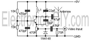
The video transmissions from this unit can be received on a small portable, tunable, and battery-operated TV set, similar to those found in flea markets. The described unit is capable of transmitting video signals that can be captured by compact,...
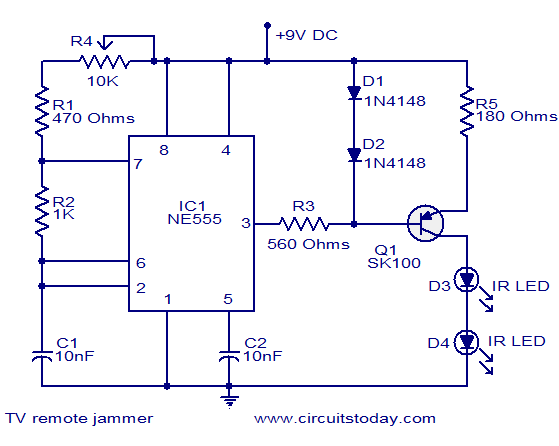
Here is the circuit diagram of simple but highly effective TV remote jammer circuit. Most of the TV remotes have 38KHz operating frequency. A flood of IR beams in the same frequency can easily confuse the TV receiver and...
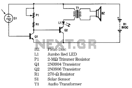
The infrared remote-control tester employs a sensitive PN-type solar sensor directly connected to a Darlington amplifier composed of transistors Q1 and Q2. Biasing is achieved through resistor R1 and PI, a variable resistor that functions as a sensitivity control....
This circuit illustrates the BF495 transistor used in an AM transmitter radio circuit diagram. Features include a powerful AM transmitter utilizing ceramic components. The BF495 transistor is a high-frequency NPN transistor commonly used in RF applications, including AM transmitters. In...
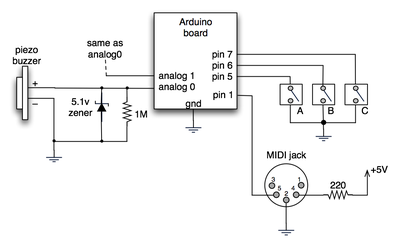
The notes for the fourth and final class are available on the Spooky Arduino class page. At the conclusion of the class, Mark from Machine Project awarded each student a merit badge. A project utilizing techniques from this week's...
Current loop analog data transmission is utilized in industrial environments due to its robustness, offering good noise immunity and the capability for wiring fault detection. Current loop analog data transmission systems are widely employed in industrial applications due to their...