
Bearing fault detector circuit diagram 1
The bearing fault detector circuit is designed to monitor the condition of bearings in machinery, ensuring that any faults are detected early to prevent further damage. The core component of this circuit is the bearing detection sensor, which senses vibrations or anomalies in the bearing's operation. This sensor outputs a signal that is processed by the signal processing circuit, which enhances the signal for better analysis.
The transistor (V) plays a crucial role in amplifying the processed signal to a level suitable for further processing or output. The audio amplifier integrated circuit (IC2) then amplifies this signal to drive the speaker (BL), which produces an audible alert when a fault is detected. The light-emitting diode (VL) serves as a visual indicator, providing a clear signal to operators when an issue arises.
The RC element is used to filter out noise and stabilize the circuit, ensuring that only relevant signals are processed. The integrated circuit (IC1) may include additional processing capabilities, such as signal conditioning or further amplification.
The adjustable resistors, RP1 and RP2, allow for fine-tuning of the circuit's sensitivity and response characteristics. RP1 adjusts the sensitivity of the signal processing circuit, enabling the detection of faults at varying thresholds, while RP2 provides additional adjustment capabilities to optimize performance based on specific operational conditions.
Overall, this bearing fault detector circuit is an essential tool for predictive maintenance in industrial applications, enhancing the reliability and efficiency of machinery by providing timely alerts of potential bearing failures.The bearing fault detector circuit is composed of the bearing detection sensor, signal processing circuit, transistor V, audio amplifier integrated circuit IC2, speaker BL and the RC element, and IC1, light-emitting diode VL, transistor are shown as the chart. RP1 is used to adjust the sensitivity of the signal processing circuit. RP2 is used to adjust the s.. 🔗 External reference
Related Circuits
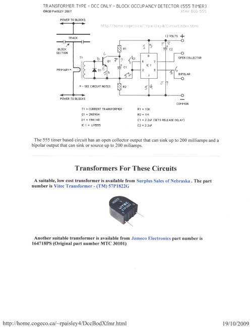
This article falls under the "you can do it too" category. It is not as difficult as one might imagine for the average model railroader, especially with the information available online and articles like this to guide the process....
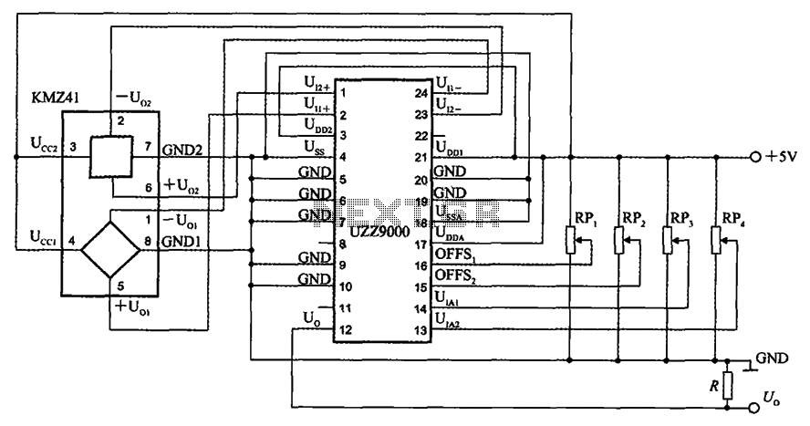
The UZZ9000 KMZ41 detection circuit is configured based on the voltage output type and angle. It operates with a +5V power supply. Potentiometers RP1 and RP2 are used for offset voltage adjustment, while potentiometers RP3 and RP4 are utilized...
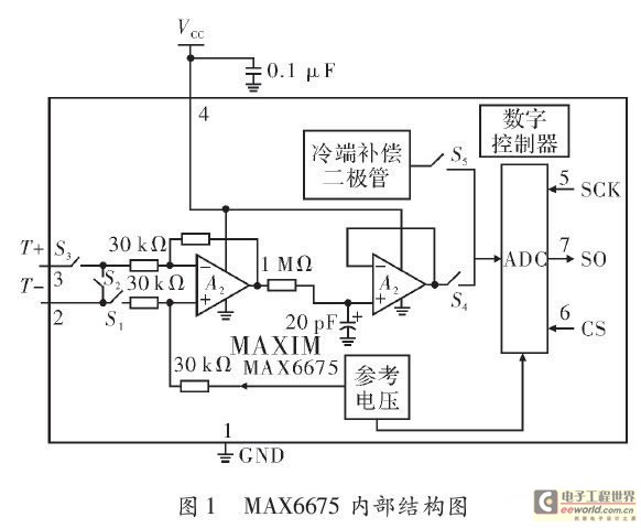
The K-type thermocouple is a commonly used temperature sensor in industrial production and scientific experiments. It can measure temperatures ranging from 0 to 1300 degrees Celsius in various applications, including direct measurements of gas, liquid, and solid surfaces. Its...
The goal is to utilize a PC to measure the outdoor temperature using a serial-connected device equipped with a probe that can be conveniently placed outside. Although various options were found through online searches, many appear to be overly...
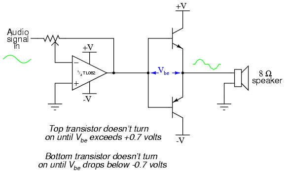
This project is an audio amplifier designed to amplify output signals from small radios, tape players, CD players, or other audio signal sources. For stereo operation, two identical amplifiers must be constructed—one for the left channel and another for...
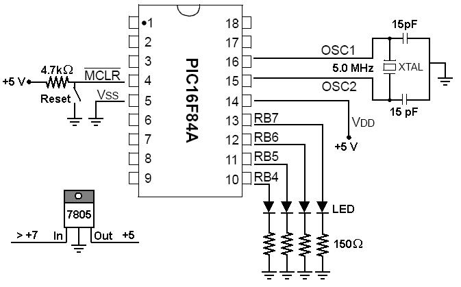
To start working with microcontrollers, several essential items are required. The PICSTART Plus kit, part number DV003001, was purchased from Microchip. This kit contains a sample PIC16F84 microcontroller chip, which in this case is a PIC16F84A chip. This chip...
Warning: include(partials/cookie-banner.php): Failed to open stream: Permission denied in /var/www/html/nextgr/view-circuit.php on line 713
Warning: include(): Failed opening 'partials/cookie-banner.php' for inclusion (include_path='.:/usr/share/php') in /var/www/html/nextgr/view-circuit.php on line 713