
DCC Detectors Construction For Model Railroad Signals
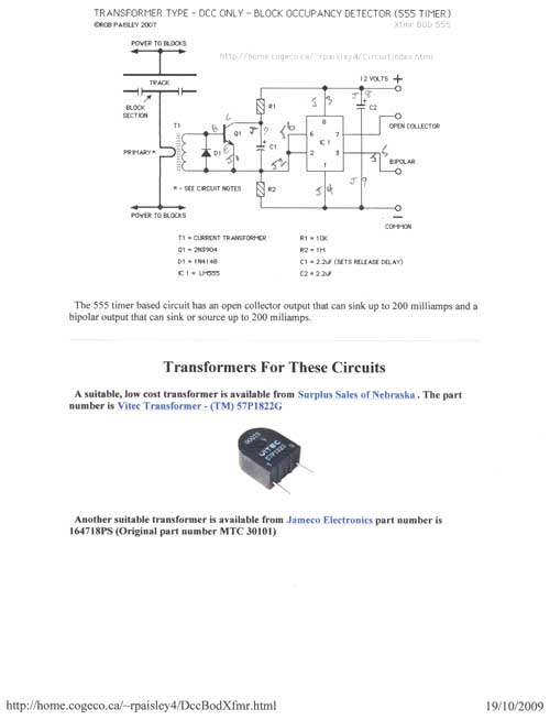
The circuit design for the DCC detector involves two primary components: a transformer for detecting occupancy and a comparator for processing the signal. The transformer is placed in series with the track, allowing it to sense the current change caused by a train passing over. The 555 timer circuit can be used for simple timing functions, while the 339 comparator circuit is more complex and allows for dual-channel detection. The output from the comparator can be connected to signal controllers, which will then manage the visual signals displayed on the layout.
The stripboard layout requires careful planning to ensure that the components are correctly placed and that the traces are cut accurately. The design should also consider power distribution and signal integrity, ensuring that the detectors operate reliably under varying load conditions. Proper soldering techniques are crucial to ensure good electrical connections and to prevent issues such as cold solder joints, which can lead to intermittent failures.
In summary, the project encompasses the design and construction of DCC-compatible block occupancy detectors, emphasizing the importance of methodical planning, component selection, and circuit layout for successful implementation in model railroad applications.This article is in the "you can do it too" category. It`s not as difficult as you can imagine for the average model railroader, especially with the information available on the Internet and with articles like this to guide you. I have been looking for a way to construct my own detectors and signal circuits to keep the cost down.
Also, there`s a lo t of satisfaction that comes from proving to yourself that you can do it. I don`t know a lot about electronics, but I can follow a schematic, I can read a meter, and I know how to solder. The rest falls into the category of "take it one step at a time and doublecheck what you`re doing". Sometimes this is referred to as a "smoke test". You don`t want to see smoke! Bill Payne, fellow member at our Nottawasaga Model Railroad Club (NMRC) knows more about electronics than I do so he is taking the lead on this project.
The NMRC layout has just been upgraded to DCC and we would also like to install signals on the layout. There`s nothing like changing signals to keep people fascinated at train shows, even if the indications of the signals aren`t quite right!
Before Christmas, 2009, Bill and I had already built and tested some signal circuits we had found on the Internet. The next step was to build some detector circuits that would work for DCC. The ones we are working with were designed by R. Paisley. One of the block occupancy detectors is designed around a 555 timer and the other is based on a 339 comparator.
Both take power directly from one rail. The wire with the power passes through the hole in a small transformer. The transformer detects a change in voltage when a train occupies a block and passes this information to the signal controllers. That`s sort of a non-electronic way of describing what`s going on. Here are the circuits by R. Paisley. We found that both work about the same. Bill is trying to see if they will also work for DC on his home layout that is not DCC. The sensitivity of the transformers for detecting the current change can be changed by the number of loops in the wire through the center hole.
The second schematic for DCC detectors shown above is based around a 339 comparator. You can buy a single comparator chip, I beileve it`s the 393. The 339, being a dual, allows more circuits to be built on one board. Bill laid out four DCC detectors on one piece of stripboard. This is where you really have to take your time. He started by laying out the circuit on paper using a Stripboard Planning Sheet. This paper layout shows where to insert components for the DCC detectors. The red dots on the plan indicate where to cut the traces on the copper side of the board. Bill kept the top line on one side of the board for 12+ volts and the first line on the opposite side is 12- volts. Once he was satisfied that the paper plan matched the schematic he turned the board over and carefully cut the traces by using a drill bit in a Dremel.
You can also use an X-Acto blade, but Bill feels the drill bit is a better guarantee that the trace is cut all the way through. If you mess up, you can always add a jumper wire. Bill laid out 4 blocks on one piece of stripboard. This is the final "beta-test" board we used to drive the signal logic. We used a couple of alligator clips to live rails on the main layout (actually at Utopia East which is near the workbench).
The 12 volt power for the circuits is supplied by a simple DC power pack that came with a President`s Choice train set. We used a meter to adjust the voltage to close to 12 volts. Last night (January 27, 2010), while my other operators played with the trains on my Utopia Northern layout, Bill and I fired up the circuit.
Well, not really "fired up". No smoke! One block wasn`t working properly. We traced it to two pads for the chip that hadn`t been soldered. For our setup I used an old 3-foot piece of HO track. How old You guess. Fiber ties, brass rails stapled to the fiber ties. 🔗 External reference
Related Circuits
A 555 timer (U1) is configured as an astable multivibrator (oscillator) with a duty cycle of 400:1 and a frequency of 40 Hz. When power is applied to the circuit, capacitor C1 (connected to pin 6 of U1) is...
Model SimpleSolenoid is a simple network model of a lifting magnet with a planar armature end face. The parameters include: Resistance R = 10 (Armature coil resistance); Number of turns N = 957; Yoke parameters such as outer yoke...
The DC motor E inversion control circuit utilizes a loop configuration with various relay contacts. It employs a single set of normally open/normally closed relay contacts. When both inputs A and B are low, relay KI is activated. In...
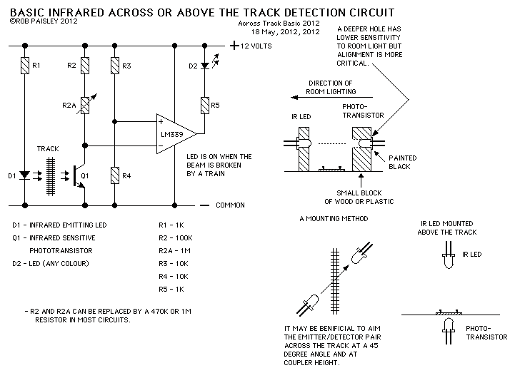
This page presents information on infrared - Across The Track train detection circuits. The circuits are designed around the LM339 comparator chip and can use a wide assortment of matched infrared - emitter / detector pairs. The basic circuit...
This circuit is designed for liquid level or proximity detection. It operates by measuring the distance to a target through the reflection of an infrared beam. The device can detect the level of liquid in a tank without any...
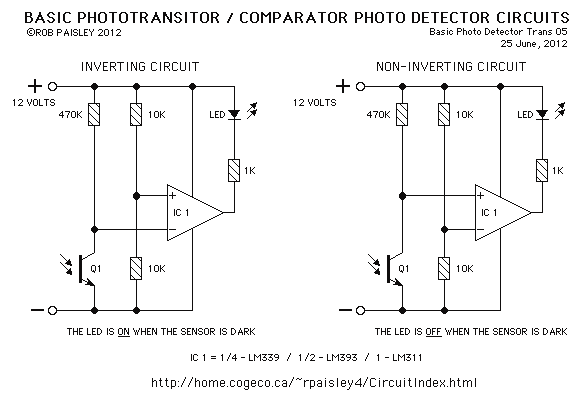
The sensors used are silicon phototransistors and Cadmium Sulfide (CdS) photocells. Both of these sensors allow less current to flow when they are dark than when lighted. Phototransistors change their conductance while photocells change their resistance depending on the...