
Mosfet Buffer Amplifier Circuit

The circuit employs a Metal-Oxide-Semiconductor Field-Effect Transistor (MOSFET) configured as a buffer amplifier to achieve high input impedance and low output impedance, which is essential for effective signal transmission without distortion. The choice of a toroidal transformer (T1) is crucial for maintaining efficiency and minimizing electromagnetic interference, as toroidal cores provide a compact and effective magnetic path.
The transformer’s primary winding is designed with 18 turns, which is optimized for the specified frequency of 4 MHz. The secondary winding, with 4 turns, maintains the desired turns ratio of 4:1. This ratio is vital for impedance matching to the load, ensuring that maximum power transfer occurs. The load impedance of 50 ohms is standard for many RF applications, making this configuration suitable for integration into various systems.
The gain of approximately 14 dB indicates that the output voltage is significantly amplified relative to the input, providing the necessary signal strength for further processing or transmission. This design is particularly advantageous in applications requiring wide bandwidth and minimal signal degradation, such as in RF amplifiers and communication systems. The careful selection of materials and winding configurations contributes to the overall performance and reliability of the buffer amplifier circuit. A MOSFET is used as a wideband buffer amplifier. T1 is wound on a toroid of approximately /f diameter, with material suitable for frequency (usually 1- to 20-MHz range). The turns ratio should be about 4:1 depending on load impedance. Typically, at 4 MHz, there are 18 turns on the primary, 4 turns on the secondary, and the stage gain is about 14-dB voltage (ZL - 50 ).
Related Circuits
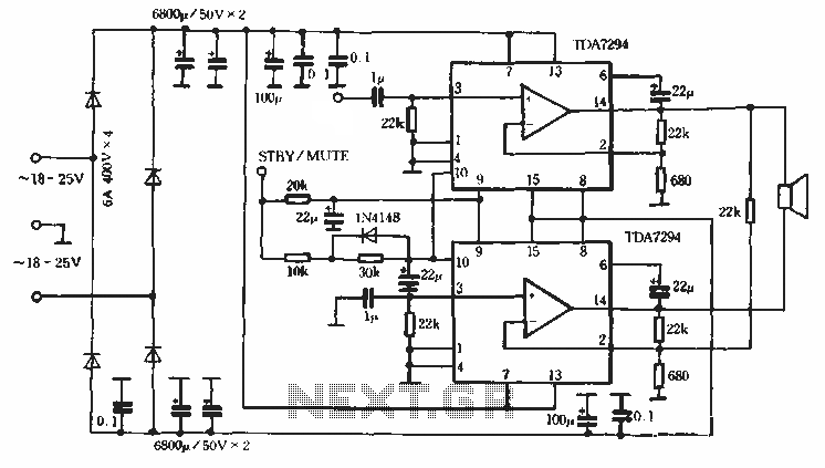
Europe's leading SGS-THOMSON STMicroelectronics recently introduced a new power integrated amplifier, the TDA7294, to the Chinese mainland market. This amplifier, characterized by a cold and hard tone, is particularly suited for Hi-Fi applications such as home theaters and active...
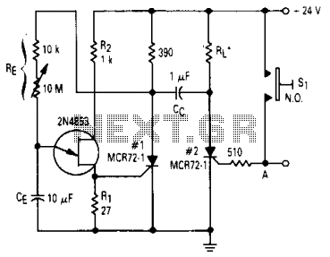
After one cycle of operation, SCR1 will be activated, resulting in a low voltage being applied to the UJT emitter circuit, which interrupts the tuning function. When pushbutton SI is pressed, or a positive pulse is applied at point...
This is a schematic diagram of a stereo audio amplifier for a car. The circuit is powered by a single IC, the TDA1553, along with some external components. This IC is designed to manage the stereo car audio system....
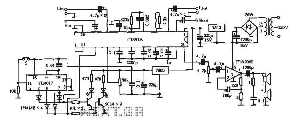
The surround processing section C1891A is a product from Sony Corporation of Japan that features a four-dimensional home theater surround processing circuit. It includes a parent roll phase-shifting circuit and a matrix surround sound amplifier. Additionally, it provides three...
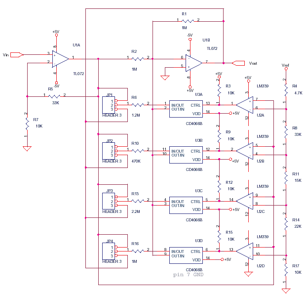
This circuit adjusts the gain of operational amplifier U1B in four distinct steps or segments. It is designed to achieve a linear output from various transducers at levels of 1%. Operational amplifier U1A serves as a buffering amplifier to...
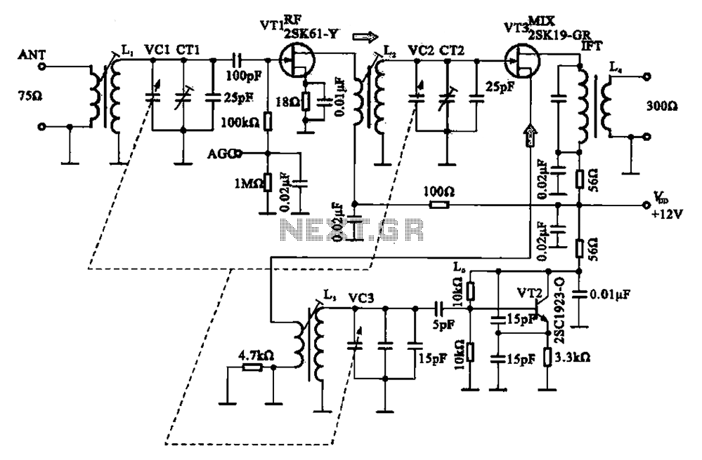
The FM radio circuit consists of a high-frequency amplifier (VT1), a mixer and local oscillator (VT2), and additional components. The circuit includes an FM radio antenna for signal detection, with an input transformer (L1) connected to a gate transistor...