
Touch Sensor Circuit

The circuit operates on a simple principle of touch sensitivity, employing a red wire and a blue wire as the primary touch sensors. The circuit is designed to be powered by a 9-volt battery or an equivalent power supply, which is critical for ensuring proper operation. The LED serves as an output indicator, visually confirming that the circuit is active.
When the wires are not in contact, the circuit remains open, and no current flows through the LED. Upon contact, the human body introduces a conductive path that completes the circuit, allowing a small amount of current to flow. This current is typically too low to cause any harm due to the high resistance of the human body. The transistor in the circuit plays a vital role in amplifying this small current, allowing it to drive the LED effectively.
It is essential to select components that match the specifications outlined in the project to avoid malfunction. If the voltage supplied exceeds the specified limit, the LED may illuminate without any physical contact, negating the intended touch-sensitive functionality. Additionally, excessive bias voltage can lead to transistor failure, where the collector inadvertently conducts to the emitter, resulting in unintended operation. Conversely, if the voltage is below the required threshold, the circuit will not activate even when the wires are touched, as the current will not be sufficient to light the LED.
In summary, this touch-sensitive circuit illustrates fundamental electronic principles, including the role of resistance, current flow, and the function of transistors in amplifying signals. Proper assembly and adherence to voltage specifications are critical for the successful operation of this circuit.In this project we`re going to use use two wires, in this project, we use one red and the other blue, which serve as the touch sensor wires. When a person touches both wires, the circuit is then closed and current runs through the circuit and lights the LED.
For the power source, you can either use a 9-volt battery or you can use a power supply to supply the 9 volts. When the wires aren`t touched, the circuit is not closed and, thus, no current can pass through the circuit. When a user touches the wires, he closes the circuit, so now current can pass through and light the LED.
The person`s body acts as the closer of the circuit. Because a person offers so much resistance, the current is very small and doesn`t cause any shock. But the small current is amplified by the transistor and thus it`s sufficient current to light an LED. Problems can arise while doing this circuit, so this is why it`s recommended that you use the exact parts or as close as possible.
First of all, if you place too much voltage into the circuit, the LED will light up without you even touching the wires. This defeats the whole purpose of having touch sensor. Under too much bias voltage provided into the circuit, the collector of the transistor breaks down and conducts across into the emitter, even without any base current at all.
This is why the levels need to set up exactly, or else this circuit may not function. In the same way, too little voltage will not make the circuit function as well. If too little voltage is used, even when you touch the wires, the LED will not light, because the current isn`t sufficient to light the LED. 🔗 External reference
Related Circuits
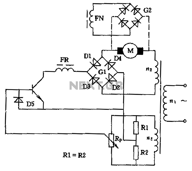
The circuit is designed to control the speed and direction of low-power DC motors, including series and shunt motors. It utilizes a rectifier bridge (G1) connected in series with the motor and linked to the secondary winding (n2) of...
This is an electric thermometer circuit composed of the LM134. In the circuit, the voltage or current output by the LM134 is proportional to the thermodynamic temperature, which can be read on a 100 µA meter. The test temperature...

Wireless audio and visual transmission to a TV. The TV functions as a receiver, eliminating the need for a separate monitor. It can also be connected to a VCR or CCD camera, enabling the setup of a remote CCTV...

The circuit principle is illustrated in the accompanying figure. When the night light shines on the photosensitive resistor RG, it exhibits a high resistance (significantly greater than 50K). As a result, the output of the LSE pin is low,...
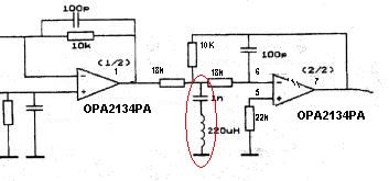
Can someone explain why there is an LC filter in the op-amp circuit? Additionally, are there any modifications that can be made to enhance the sound quality? The presence of an LC filter in an operational amplifier (op-amp) circuit serves...
This circuit utilizes the TLC555CP timer integrated circuit to flash an LED approximately twice per second. This specific 555 timer operates on a voltage of only 3 volts, allowing it to be powered by two 1.5-volt cells. When using...